Limitorque Actuation Systems L120 Series FCD LMENIM1201-05-A4 – 03/18
24
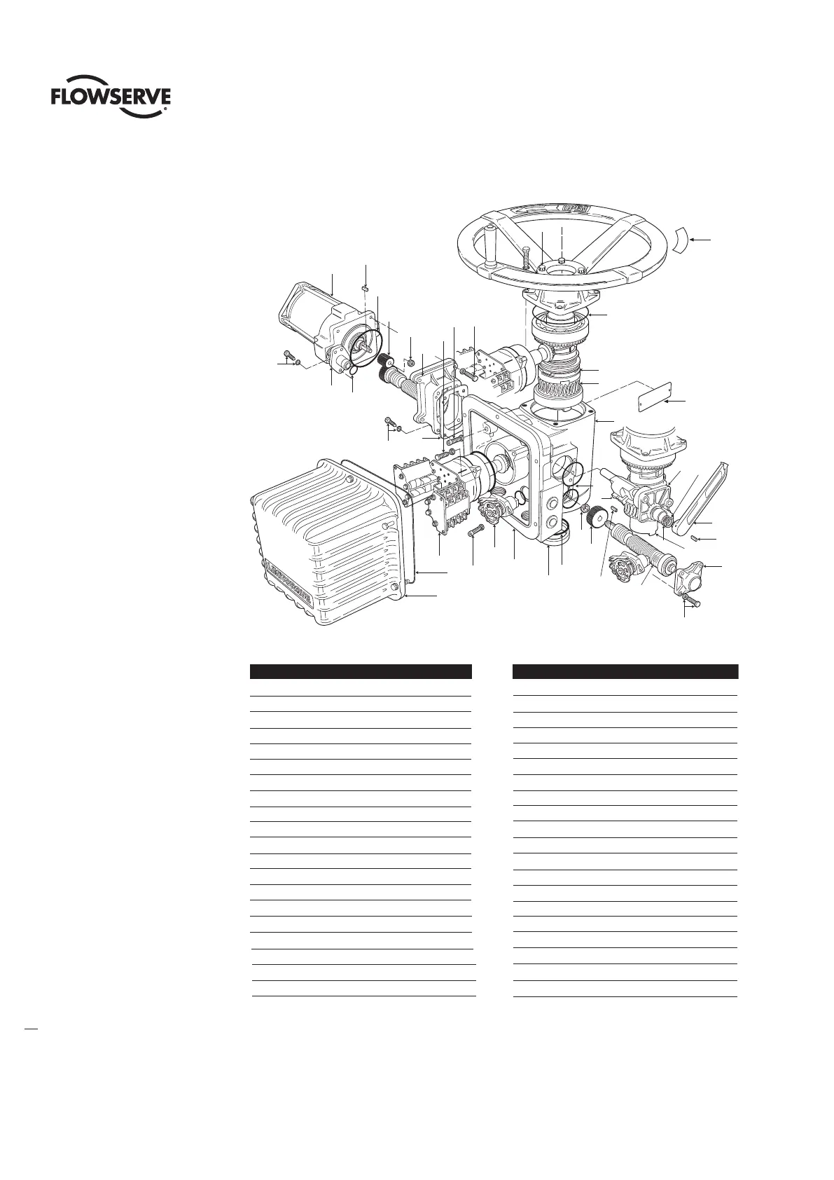
Figure 5.2 (two of two) – L120-10 through 40 parts breakdown
39
42/7*
31
40
50
50
38
30
50
46
50
50
42/5
1
11
9
5
50
50
35
37
36
4
42/9
42/3
3
200
47
50
300
305
7
310
312
2
9
15
42/11
21
19
10
25
42/6
Piece Quantity Description
11 Housing
21 Motor Adapter
31 Electrical Compartment
41 Seal Retainer
51 Worm Shaft End Cap
6 1** HSG. Cover Shim Set
71 Declutch Shaft Assembly
91 Declutch Lever
10 1 Roll Pin
11 1 Declutch Cap
15 1Worm Shaft Assembly
19 1 Clutch Sleeve
21 1Worm Gear
25 1 Drive Sleeve
30 1 Nipple Flange
31 1 Motor
32 4** Dowels
Piece Quantity Description
35 1Worm Shaft Gear
36 1 Key
37 1 Flexloc Nut
38 1 Motor Pinion
39 1 Key
40 1 Stop Nut
41 1** Washer
42 1 Seals Kit
42/7 1 O-ring Mtr
42/7* 1 Gasket Mtr
42/3 1 Gasket – Mtr Adapter
42/11 1 O-Ring – Handwheel Mounting
42/9 1 Seal – Drive Sleeve
42/5 1 O-ring – Declutch Assembly
42/6 1 O-ring – Declutch Lever
* L120-40 Only
46 1 O-ring / Motor Nipple
47 1 O-ring / Cover
50 1 Hardware Kit
200 1 Compartment Cover
300 1Torque Switch
305 1 Geared Limit Switch
310 1 Unit Nameplate
312 1 Rimpull Nameplate