E119-P
FW_E119-P_M_v0301-02_EN Page 33
7 ANALOG OUTPUT
7.5 CUT-OFF
A low flow cut-off can be set as a percentage of the full range of 16 mA, for
example, to ignore leakage.
When the flow is less than the required rate, the current will be the
minimum signal (4 mA, or 20mA when the analog output is programmed
‘up-side-down’).
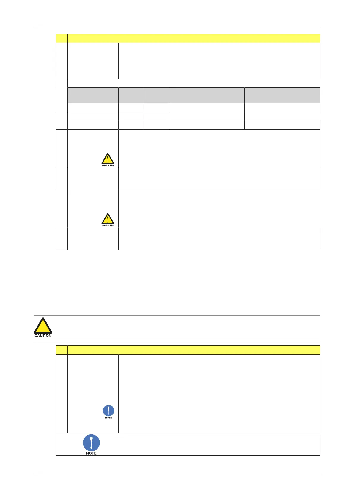
CUT-OFF CALCULATION EXAMPLES
Cut-off Rate-min
4 mA
Rate-max
20 mA
Required rate
before reading
Output
at required rate
2.0% 0 L/min 100 L/min (100-0)*2.0% + 0 = 2.0 L/min 4 + (16*2.0%) = 4.32 mA
3.5% 20 L/min 800 L/min (800-20)*3.5% + 20 = 27.3 L/min 4 + (16*3.5%) = 4.56 mA
3.5% up-side-down 800 L/min 20 L/min (800-20)*3.5% + 20 = 27.3 L/min 20 - (16*3.5%) = 19.44 mA
7.6 TUNE MIN (4MA)
Use this setting to precisely tune the minimum analog output value (initial
value is 4 mA). This value can differ slightly due to ambient influences such
as temperature.
Before tuning the signal, make sure the analog signal is not being
used for any application.
After pressing PROG, the current will be about 4 mA. The current can be
increased / decreased with the arrow-keys and is directly active. Press
PROG to store the new value.
7.7 TUNE MAX (20MA)
Use this setting to precisely tune the maximum analog output value (initial
value is 20 mA). This value can differ slightly due to ambient influences
such as temperature.
Before tuning the signal, make sure the analog signal is not being
used for any application.
After pressing PROG, the current will be about 20 mA. The current can be
increased / decreased with the arrow-keys and is directly active. Press
PROG to store the new value.
5.5.8 MENU 8: PULSE OUTPUT
The “Pulse” menu configures the behavior of the digital output signals. As standard, one transistor
output is available (Type OT): D1. Its function is based on the mode selected at 8.1: PULSE OUTPUT >
MODE.
Optionally, one relay output is available (Type OR): D5. Its output functionality corresponds to the
functionality of output D1.
The digital (transistor) output D1 has a maximum frequency of 500 Hz (scaled pulse output).
Make sure the output frequency of the optional digital (relay) output D5 does not exceed 0.5 Hz,
otherwise the relay lifetime and reliability will be reduced significantly.
8 PULSE OUTPUT
8.1 MODE
The following modes of operation are available for the digital outputs:
● Disabled: the output is switched off.
● Scaled: each time the accumulated total has increased with the Amount
set at 8.3: PULSE OUTPUT > AMOUNT, a pulse will be sent on the output with
the Width set at 8.2: PULSE OUTPUT > WIDTH.
● Retransmit: the unscaled incoming pulse from the flowmeter is
retransmitted on the output.
The Retransmit mode is often used when sinus / non-square wave input
signals are present (for example, coil signals) that need to be transmitted as
robust square wave forms. The max. frequency is 10kHz with 50% duty
cycle and a minimum on and off time of 50µs.
When Retransmit is selected, the menus 8.2: PULSE OUTPUT > WIDTH and
8.3: PULSE OUTPUT > AMOUNT will disappear.