E119-P
Page 50 FW_E119-P_M_v0301-02_EN
Power supply 10 – 30 V DC (OFF = right position)
J1 J2 External sensor supply voltage Required supply voltage
ON ON 8.2 V DC (max. output 20 mA) 9 – 27 V DC
ON OFF 12 V DC (max. output 30 mA) 13 – 27 V DC
OFF OFF Supply voltage - 1 V DC (max output 75 mA) Up to 27 V DC
Power overload
The sensor supply is protected against a power overload but an overload may affect the functionality
of the unit (i.e. shutdown).
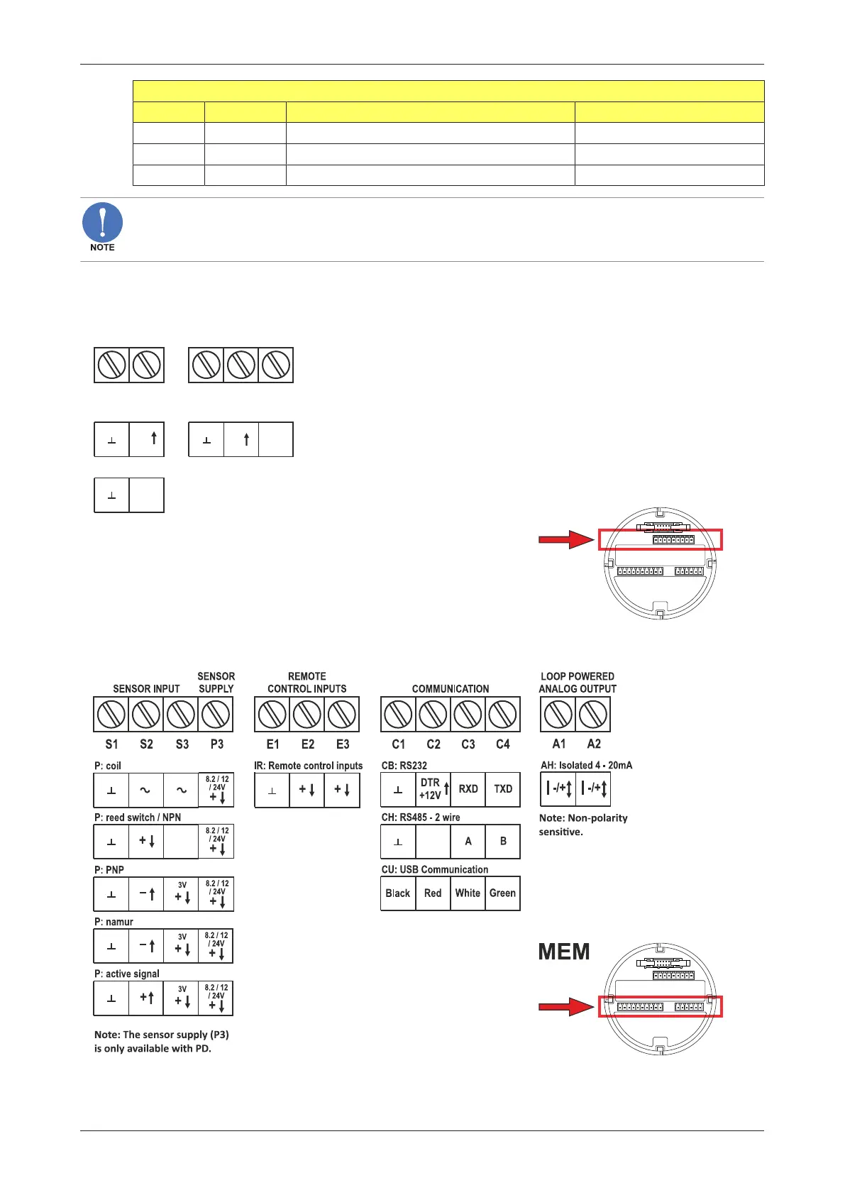
6.4.5 TERMINAL CONNECTORS – MEM
The following terminal connectors are available for the Main Electronics Modus (MEM).
P2
POWER
REQUIREMENTS
P1
PX: 9 - 27V DC
PD: 9 - 27V DC
R1 R2
PULSE OUTPUT
D1
R3
+
+
OT: passive transistor output
+
PB: battery powered
(PX: is standard available: if supply PX/PD
is connected, the battery supply will be
switched off automatically.
MEM
Fig.28: Terminal connectors MEM - upper row
Fig.29: Terminal connectors MEM - lower row