E119-P
FW_E119-P_M_v0301-02_EN Page 49
Type Input
Supply voltage
range
Maximum supply
current
Remarks
PD-OR P6 24-27 VDC 110 mA With relay(s) and sensor supply
PD-OT P2 9-27 VDC 75 mA Without relay(s), with sensor supply
PX P2 9-27 VDC 50 mA Without relay(s) and sensor supply
AH A1/A2 11-27 VDC 25 mA Analog output circuit that also
powers the unit. Requires an
additional supply on input P6 or P2
when combined with relay(s), sensor
supply or backlight.
Only use terminal P2 when terminal P6 is not present.
Relays outputs (Type OR)
The relays (up to two) that come with Type OR have the following contact ratings, which should be
used to select a suitable power supply and overcurrent protection for the circuits connected to the
relay outputs R8 to R11:
Load type & voltage Voltage
Maximum switch
current
Resistive load at 30 VDC, 125 VAC, 250 VAC. Max. 2 A
Inductive load (for pilot duty applications) 30 VDC, 125 VAC, 250 VAC. Max. 0.5 A
The relays shall be suitably protected for their ratings not to be exceeded. This shall be considered
in the end use.
6.4.4 VOLTAGE SELECTION SENSOR SUPPLY
Type PB / PX – Pickup element supply
Terminal S3 provides a limited supply voltage of 3.2 VDC (coil signals 1.2 V) for the flowmeter signal
output. Output impedance is 2700 ohms and power is limited to 3.3 mW under short circuit
conditions.
Limited power
This voltage MAY NOT be used to power the flowmeter electronics, converters, etc. as it will not
provide adequate sustained power! All energy used by the flowmeter pickup will directly influence
battery life (type PB). It is strongly advised to use a “zero power” pickup such as a coil or reed-
switch when operating without external power. You can use some low power NPN or PNP output
signals, but battery life will be significantly reduced (consult your distributor).
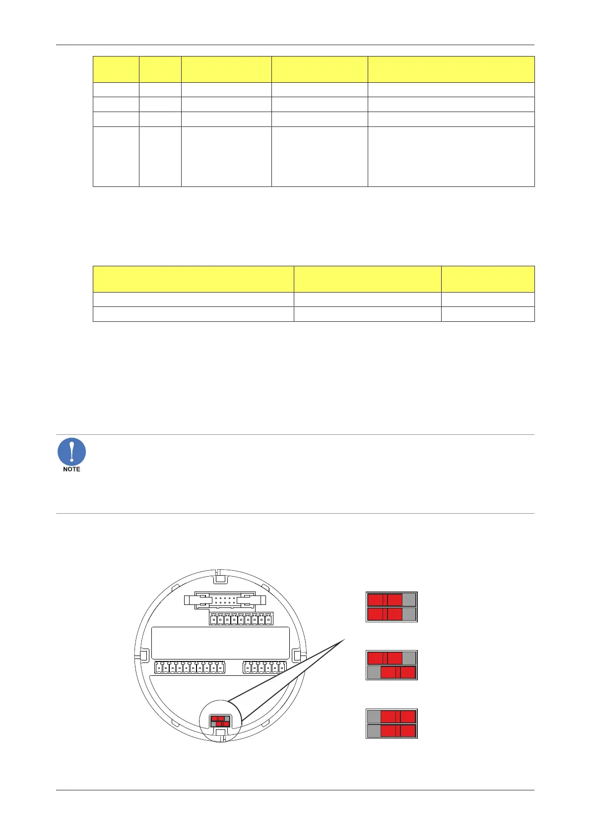
Type PD: Sensor supply: 8.2 VDC – 12 VDC or 24 VDC (Vin P2 minus 1 V)
This option provides a supply derived from the input supply. Adjust the P3 output voltage using
switches J1 and J2 on the bottom rear of the MEM (Main Electronics Module) - see following figure.
V input - 1V DC
8.2VDC
12VDC
J1
J2
J1
J2
J1
J2
on off
Fig.27: Voltage selector switch (terminal connector P3)