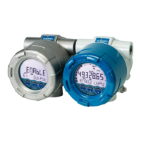
E119-P
FW_E119-P_M_v0301-02_EN Page 55
Active signals 8.2 V and 24 V
The unit is suitable for flowmeters with an Active signal. The detection levels are about 50% of the
selected supply voltage; approximately 4 V (ACT_8.1) or 12 V (ACT_24). See
4:
FLOWMETER[»29] for more information.
Active signal selection may be desired in the case of power supply type PD being supplied for
sensor supply.
S1
S2
P3
↓
+
J1-J2
8.2 ; 12V; 24VV
Common system ground
R
┴
act
S3
MEM
Fig.38: Terminals S1-S2 and P3: Active signal inputs 8.2 V and 24 V
6.4.11 TERMINALS E1-E3: REMOTE CONTROL INPUTS - TYPE IR
Two remote control inputs are available that can be activated with an external switch (pushbutton).
When a falling edge is detected (the moment the switch closes) on an input, the function assigned to
it in
6: REMOTE CONTROL INPUTS[»31] is executed.
When the function “Clear Total” or “End Delivery” is assigned, the corresponding function through
the optical keys can be disabled by keeping the assigned remote control input closed.
Make sure the contact resistance of the switch is less than 0.8 V@2uA = 400 kOhm. The closing
action should last for at least 100 ms. The input must be switched with a normally open contact to
GND.
Fig.39: Terminals E1-E3: Remote control inputs
6.4.12 TERMINALS A1-A2: ISOLATED ANALOG OUTPUT – TYPE AH
The flowrate proportional output (AH) is standard available. This output is an isolated 4-20mA
output with the possibility to power the device via the 4-20mA loop. It is non-polarity sensitive.

 Loading...