1652C/1653B/1654B
Calibration Manual
2
Precautions and Safety Information
If this product is used in a manner not specified by the manufacturer, the protection
provided by the Tester may be impaired.
Read the Safety Information page before servicing the Tester.
In this manual, a Warning identifies conditions and actions that pose hazard(s) to the
user. A Caution identifies conditions and actions that may damage the Tester or the test
instruments.
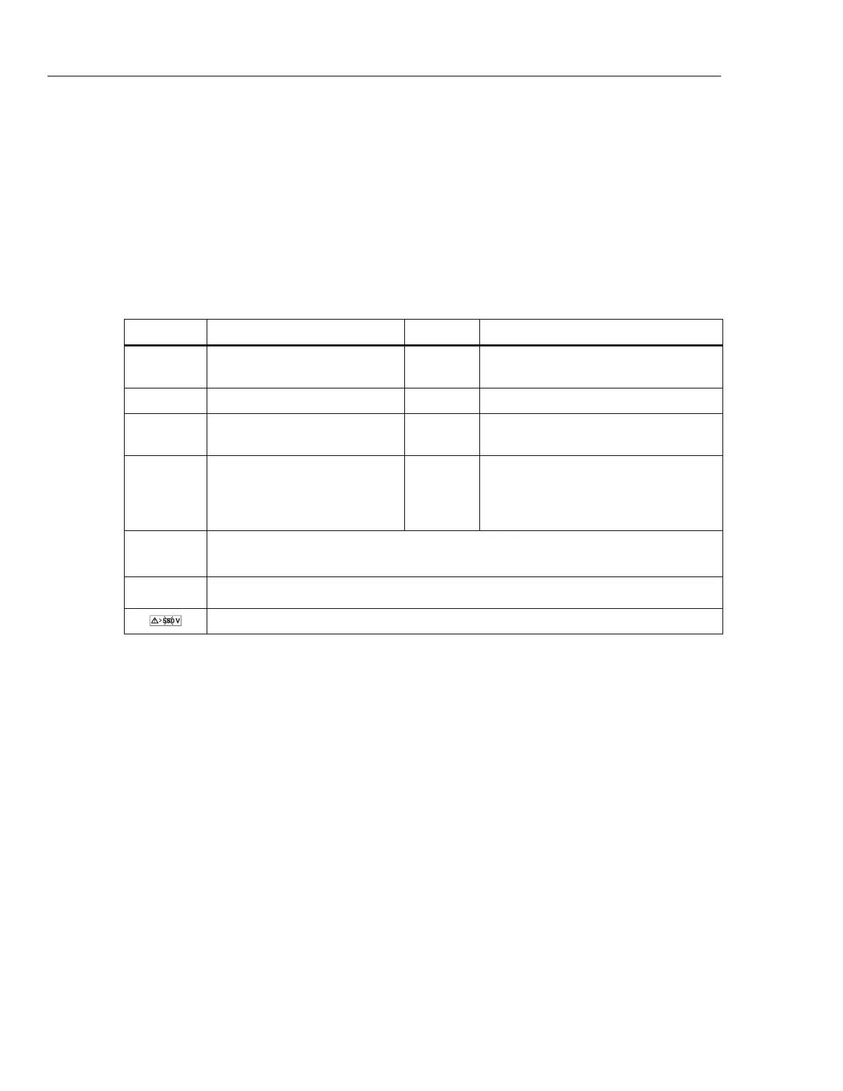
Symbols used on the Tester and in this manual are explained in Table 1.
Table 1. Symbols
Symbol Description Symbol Description
Fuse
Hazardous voltage. Risk of electrical
shock.
Double Insulated. Earth Ground
Risk of Danger. Important
information. See Manual.
Conforms to relevant European standard.
S
Do not dispose of this product as
unsorted municipal waste. Go to
Fluke’s website for recycling
information.
Battery or battery compartment. Low
battery when shown on display
CAT III
CAT III equipment is designed to protect against transients in equipment in fixed-
equipment installations, such as distribution panels, feeders and short branch circuits, and
lighting systems in large buildings.
CAT IV
CAT IV equipment is designed to protect against transients from the primary supply level,
such as an electricity meter or an overhead or underground utility service.
Do not use in distribution systems with voltages higher than 550 V.