EasyManuals Logo

Fluke 1653B User Manual

Fluke 1653B
43 pages
To Next Page IconTo Next Page
To Previous Page IconTo Previous Page
Page #26 background imageLoading...
Page #26 background image
Electrical Installation Tester
Basic Maintenance
17
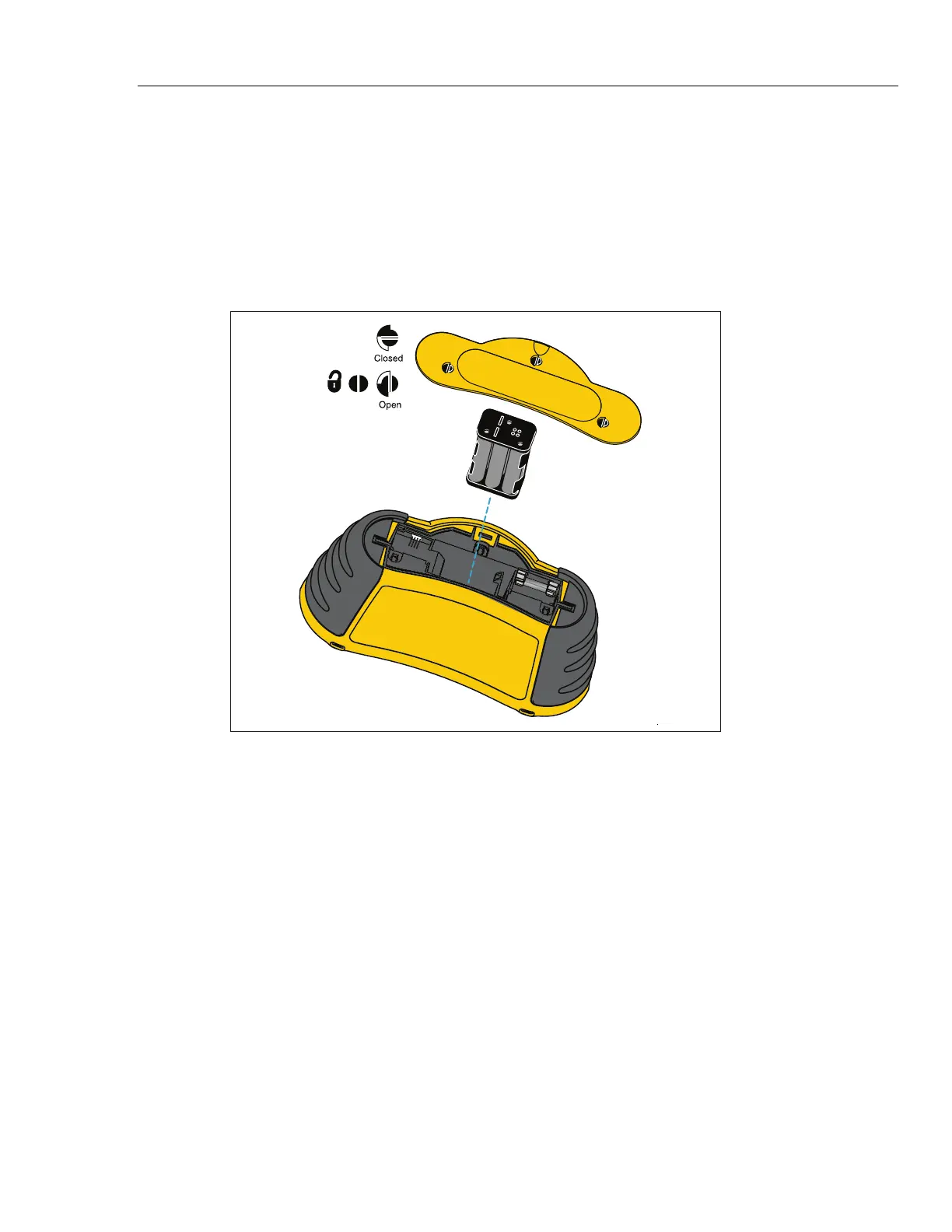
door screws (3) one-quarter turn counterclockwise.
4. Press the release latch and slide the battery holder out of the Tester.
5. Replace the batteries and the battery door.
Note
All stored data will be lost if the batteries are not replaced within
approximately one minute (1653B and 1654B only).
6. Secure the door by turning the screws one-quarter turn clockwise.
apx028f.eps
Figure 1. Battery Replacement
How to Test and Replace the Fuse
The Tester performs a fuse test each time it turns on. If leads are plugged into the L and
PE input jacks, the fuse test is skipped. If a blown fuse is detected, testing is disabled,
FUSE appears on the primary display, and the Tester issues a warning beep.
You can also perform a manual check of the fuse.
To check the fuse manually:
1. Turn the rotary switch to either . or /.
2. Short the leads.
3. Press and hold .
If the fuse is bad, FUSE will appear on the display to indicate the Tester is damaged and
needs repair. Contact Fluke Service for repair (see How to Contact Fluke).

Questions and Answers:

Question and Answer IconNeed help?

Do you have a question about the Fluke 1653B and is the answer not in the manual?

Fluke 1653B Specifications

General IconGeneral
Insulation Test Voltage50 V, 100 V, 250 V, 500 V, 1000 V
Loop and Line Resistance0.01 Ω to 1999 Ω
Loop/Line Resistance0.01 Ω to 1999 Ω
Frequency45 Hz to 65 Hz
Resistance Measurement Range0.01 Ω to 1999 Ω
Loop Impedance Measurement Range0.01 Ω to 1999 Ω
Power Supply6 x 1.5 V AA batteries
AC Voltage Range500 V
DC Voltage Range500 V
Insulation Resistance Range0.01 MΩ to 1000 MΩ
Prospective Earth Fault Current (PEFC)0 A to 20 kA
Prospective Short Circuit Current (PSC)0 A to 20 kA
RCD Trip Time300 ms
RCD Trip Current10 mA to 1000 mA
DisplayDigital
Safety CategoryCAT III 500 V, CAT IV 300 V
RCD Trip Time Measurement Range10 ms to 2000 ms
Dimensions10 cm x 25 cm x 12.5 cm
Safety StandardsEN61557

Related product manuals