Power Logger
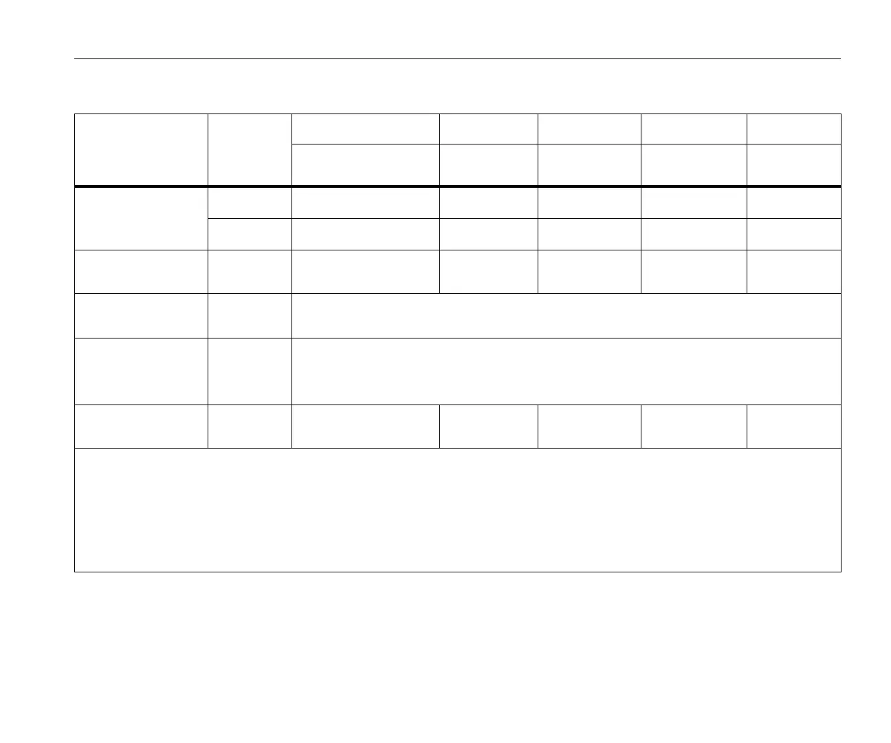
Electrical Specifications
71
Intrinsic Uncertainty ±(% of measurement value + % of power range)
Parameter
Influence
Quantity
Direct Input
[1]
iFlex1500-12 iFlex3000-24 iFlex6000-36 i40S-EL
Clamp: 50 mV/500 mV
Rogowski: 15 mV/150 mV
150 A / 1500 A 300 A / 3000 A 600 A / 6000 A 4 A / 40 A
Active Power P
Active Energy E
a
PF ≥0.99 0.5 % + 0.005 % 1.2 % + 0.005 % 1.2 % + 0.0075 % 1.7 % + 0.0075 % 1.2 % + 0.005 %
0.1≤PF <0.99 see Formula 1 see Formula 2 see Formula 3 see Formula 4 see Formula 5
Apparent Power S
Apparent Energy E
ap
0 ≤ PF ≤1 0.5 % + 0.005 % 1.2 % + 0.005 % 1.2 % + 0.0075 % 1.2 % + 0.0075 % 1.2 % + 0.005 %
Reactive Power Q
Reactive Energy E
r
0 ≤ PF ≤1 2.5 % of measured apparent power/energy
Power Factor PF
Displacement
Power Factor
DPF/cosφ
- Reading ±0.025
Additional uncertainty
(% of power high-range)
V
P-N
>250 V 0.015 % 0.015 % 0.0225 % 0.0225 % 0.015 %
[1] Only for calibration laboratories
Reference Conditions:
Environmental: 23 °C ±5 °C, instrument operating for at least 30 minutes, no external electrical/magnetic field, RH <65 %
Input conditions: CosΦ/PF=1, Sinusoidal signal f=50/60 Hz, power supply 120 V/230 V ±10 %.
Current and power specifications: Input voltage 1ph: 120 V/230 V or 3ph wye/delta: 230 V/400 V
Input current >10 % of current range
Primary conductor of clamps or Rogowski coil in center position
Temperature Coefficient: Add 0.1 x specified accuracy for each degree C above 28 °C or below 18 °C