1732/1734/1736/1738/3540 FC
Calibration Manual
22
Current Measurement
Fluke recommends using a divider with 30 Ω across the Logger input and 10 kΩ in series with high side of
the input:
• Fluke PN 2114858 (10 kΩ)
• Fluke PN 1757740 (30 Ω) – see Table 6 for the recommended assembly of this divider. Best practice is to
measure the resistor values at time of use.
Caution
Be careful when you set the calibrator output voltages. High voltages applied to the
current input will damage the Logger.
1. Connect the Voltage-to-Current Input Cable Assembly to the Power Logger current probe input. See Table 4.
2. Connect the VL1730 "N" lead to the calibrator AUX LO.
3. Connect the calibrator AUX HI output to the VL1730 L1+L2+L3 leads.
4. Stack the 173x Calibration Cable Assembly together: red to red and black to black.
Note
The verification of the 3540 FC is done on the phase currents L1/A, L2/B, L3/C.
Verification of the plugged neutral current is not supported.
5. Plug the attenuator into the calibrator Normal HI and LO.
6. Connect the stacked 173x Calibration Cable Assembly to the attenuator. Connect the black leads to
NORMAL LO.
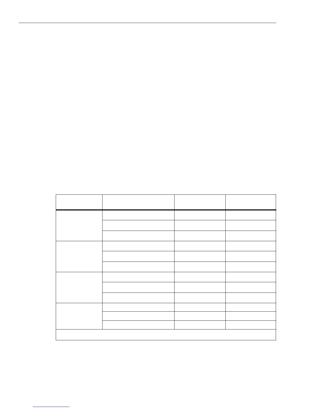
7. For all ranges in Table 11, set the calibrator to the voltages indicated in the given order. Check that the values
are between the limits.
Table 11. Flexi Current Probe Input Verification
8. When you are finished, set the calibrator to Standby.
Range
Calibrator output
[1]
(57 Hz sine wave, 5V out AUX)
Nominal Reading Logger Reading Limits
Direct Flexi Low
1.000 mV 1.000 mV 0.994…1.006
10.000 mV 10.000 mV 9.967…10.033
15.000 mV 15.000 mV 14.952…15.048
Direct Flexi High
10.00 mV 10.00 mV 9.94…10.06
100.00 mV 100.00 mV 99.67…100.33
150.00 mV 150.00 mV 149.52…150.48
Direct Clamp Low
5.00 mV 5.00 mV 4.98…5.02
10.00 mV 10.00 mV 9.97…10.03
50.00 mV 50.00 mV 49.89…50.11
Direct Clamp High
50.0 mV 50.0 mV 49.8…50.2
100.0 mV 100.0 mV 99.7…100.3
500.0 mV 500.0 mV 498.9…501.1
[1] Calibrator Output Impedance and Logger loading will effect actual voltage being applied. Use of divider and Spreadsheet
described above recommended

 Loading...