Fluke 434-II/435-II/437-II
Service Manual
4-6
Set Clamp for Phase and Neutral (select with F4) to 1 mV/A, 1000 A, x1, 1:1. To
confirm press F5 – BACK.
• Set the Analyzer in DEMO mode: press SETUP, press F1 - USER PREF, and select
DEMO ON with F2. Demo mode gives increased sensitivity at the voltage inputs.
Warning: input voltage must not exceed 2 V rms in DEMO mode!
4.7.2 Accuracy
Proceed as follows:
1. Must be checked for all phases A/L1, B/L2, C/L3, and N(eutral).
2. Set the Calibrator to 1 V, 60 Hz and STBY.
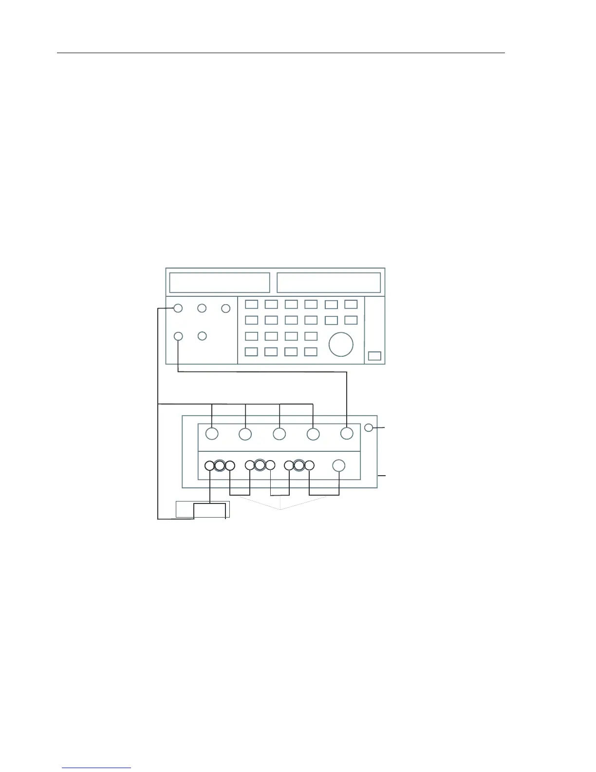
3. Connect the LO output (black) with the Ground (green) input of the Analyzer.
Connect the HI output (red) with all current (BNC) inputs and the A/L1, B/L2, C/L3,
and N voltage banana inputs of the Analyzer. Refer to Figure 4.2.
A/L1
B/L2 C/L3
N
GND
A/L1
B/L2 C/L3
N
CALIBRATOR
POWER
INPUT
BLOCK
LO
HI
NORMAL
PM 9093 PM 9093 PM 9093
PM 9082
RED
PM 9092
Figure 4-1. verification of Current Inputs
4. Set the Calibrator to OPR (Operate, indicated by a green LED in the OPR key or on
the display).
5. On the Analyzer press MENU, select Volts/Amps/Hertz, press F5 – OK to enter the
function.
6. Use the up/down arrow keys to get A rms readout in the screen area. Check for an A
rms readout between 990 ... 1010 A (tolerance 5 + 5 A = 10 A).
7. Set the Calibrator to 0 Hz, 0 V and then to OPR.
8. On the Analyzer check for a current readout A rms between 0 ... 5 A.
 Loading...