Fluke 434-II/435-II/437-II
Service Manual
4-8
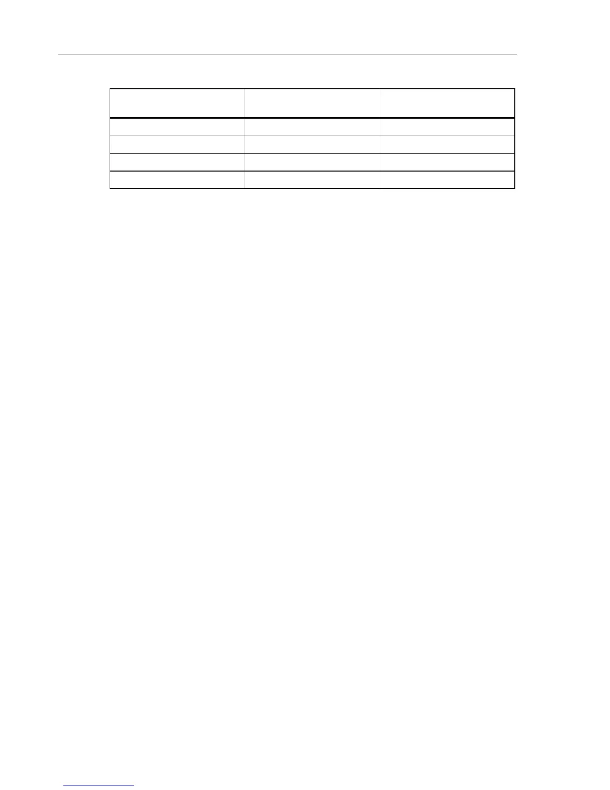
Table 4-2. Bandwidth Check of Current Channels (x1, AC + DC)
Current Channel to be verified Readout at 60 Hz (adjust
Calibrator with EDIT FIELD)
Readout at 3 kHz
A/L1 1000 A 945 A or more
B/L2 1000 A 945 A or more
C/L3 1000 A 945 A or more
N 1000 A 945 A or more
8. Set the Calibrator to STBY.
9. Switch the Analyzer’s DEMO mode to OFF.
10. Disconnect the leads from the current inputs.
4.8 Voltage Inputs
4.8.1 Introduction
WARNING
Dangerous voltages will be present on the calibration source
and connecting cables during the following steps. Ensure that
the Calibrator is in standby mode before making any
connection between the Calibrator and the Analyzer.
Proceed as follows:
1. Press SETUP, press F1 - USER PREF, and select DEMO OFF with F2.
2. To check the A/L1, B/L2, C/L3 inputs, connect the N input to Ground (See Figure 4-
3). N now will give zero reading.
 Loading...