Fluke 434-II/435-II/437-II
Service Manual
6-6
4. Remove the remaining 2 selftapping screws 8.5 mm long (total length) that fix the
Main PCA module to the top case assembly. The screws are located at the bottom
side of the keyboard.
5. Separate the Main PCA module from the top case.
6. Now you have access to LCD-module, keypad foil and keypad. They can be
separated from top case without the removal of screws or clamps. Do not touch
contact areas with your hands in order to avoid contamination (or wear cotton
gloves).
Note: when installing the LCD-module into the top case, take care that no dust or dirt
is present between module and the window/decal.
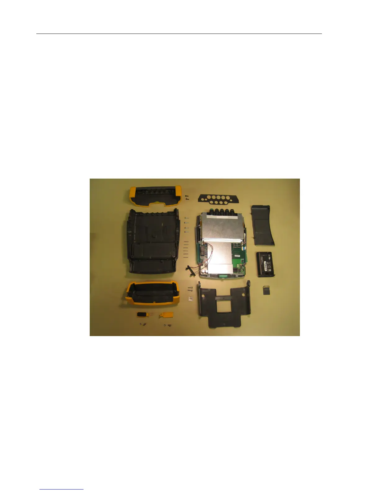
6.2.7 Pictures Showing Disassembly Steps
Note: pictures may be subject to minor changes without prior notice.
Fig. 6-1. Dismantling step 1 (bottom case removed)
 Loading...