Fluke 434-II/435-II/437-II
Service Manual
4-10
1. Set the Analyzer to 120 V, 60 Hz nominal (SETUP menu, arrow and ENTER keys).
Press MENU, select Volts/Amps/Hertz, press F5 - OK.
2. To check the A/L1, B/L2, C/L3 inputs: connect the N input to Ground (See Figure 4-
3).
3. Set the Calibrator to 60 Hz, 60 V and then to OPR.
4. Fluke 434-II: check for a voltage readout V rms between 59.4 ... 60.6 V.
Fluke 435-II/437-II: check for a voltage readout V rms between 59.88 ... 60.12 V.
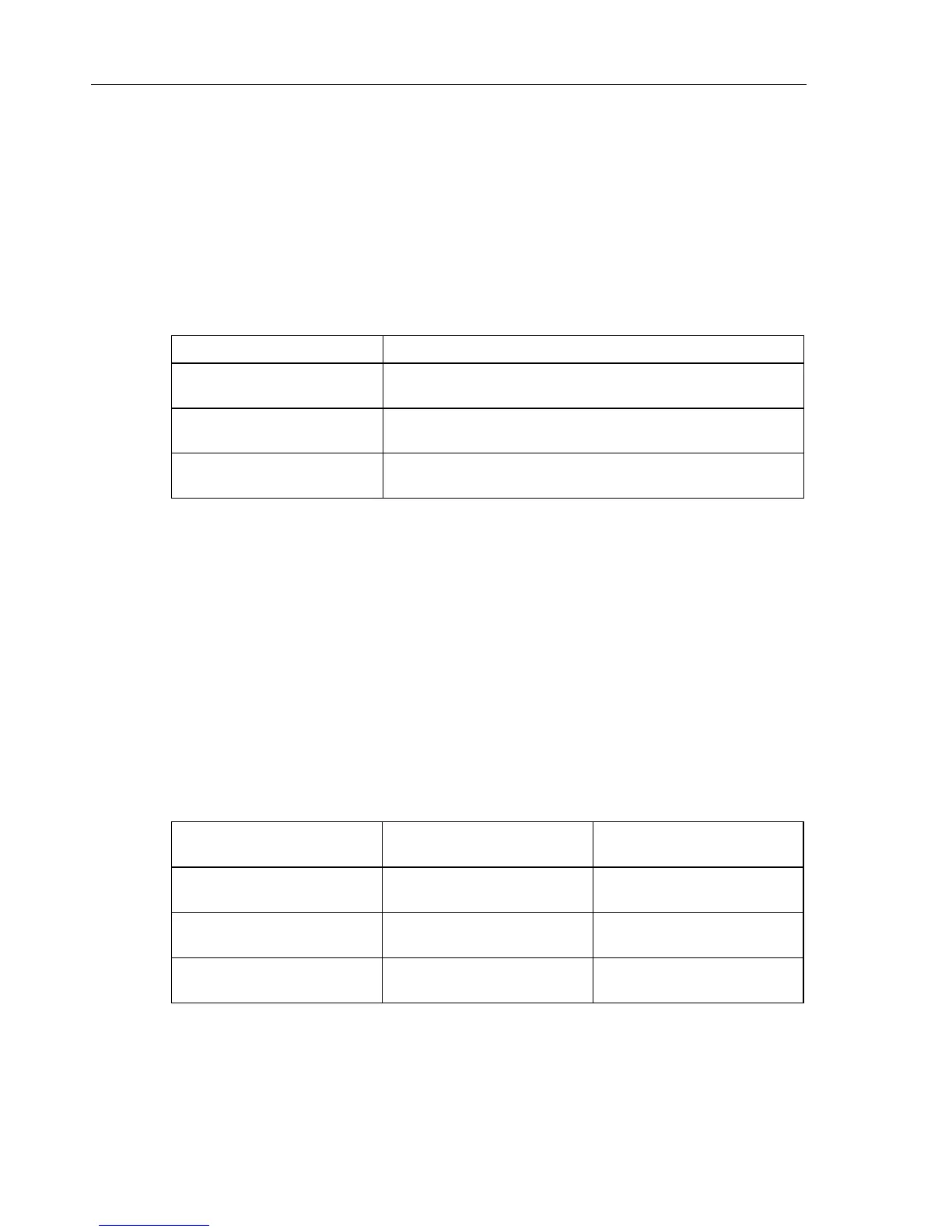
5. Check the 120 V range according to the table below.
Table 4-3. Accuracy Check of Voltage Channels A/L1, B/L2, C/L3
Set Calibrator to Readout at Voltage Channels
60 V, 60 Hz, OPR Fluke 434-II: 59.4 ... 60.6 V
Fluke 435-II /437-II: 59.88 ... 60.12 V
120 V, 60 Hz, OPR Fluke 434-II: 119.4 ... 120.6 V
Fluke 435-II /437-II: 119.88 ... 120.12 V
240 V, 60 Hz, OPR Fluke 434-II: 239.4 ... 240.6 V
Fluke 435-II /437-II: 239.88 ... 240.12 V
6. Set the Calibrator to STBY.
Optional Test. Bandwidth Check of Channel A/L1, B/L2, C/L3 (*):
7. Set the Calibrator to 120 V, 60 Hz and OPR.
8. Now check the voltage channels one by one. Use the Calibrator’s field edit function
(AMPL/FREQ key) to adjust the Calibrator to an Analyzer readout of 120.0 V /
120.00 V.
9. Increase the frequency to 3 kHz.
Fluke 434-II: check for a readout of 114.0 V or more.
Fluke 435-II/437-II: check for a readout of 114.00 V or more.
Check the channels according to the table below.
Table 4-4. Bandwidth Check of Voltage Channels A/L1, B/L2, C/L3
Voltage Channel to be verified Readout at 60 Hz (adjust
Calibrator with EDIT FIELD)
Readout at 3 kHz
A/L1 Fluke 434-II: 120.0 V
Fluke 435-II /437-II: 120.00 V
Fluke 434-II: ≥ 114.0 V
Fluke 435-II /437-II: ≥ 114.00 V
B/L2 Fluke 434-II: 120.0 V
Fluke 435-II /437-II: 120.00 V
Fluke 434-II: ≥ 114.0 V
Fluke 435-II /437-II: ≥ 114.00 V
C/L3 Fluke 434-II: 120.0 V
Fluke 435-II /437-II: 120.00 V
Fluke 434-II: ≥ 114.0 V
Fluke 435-II /437-II: ≥ 114.00 V
10. Set the Calibrator to STBY.
 Loading...