Fluke 434-II/435-II/437-II
Service Manual
4-16
5. Set the Calibrator to STBY.
Optional Test. Bandwidth Check of Channel A/L1, B/L2, C/L3 (*):
6. Set the Calibrator to 215 V, 50 Hz and OPR.
7. Now check the voltage channels one by one. Use the Calibrator’s field edit function
(AMPL/FREQ key) to adjust the Calibrator to an Analyzer readout of 215 V.
8. Increase the frequency to 3 kHz.
Fluke 435-II/437-II: check for a readout of 204.2 V or more.
Check the channels according to the table below.
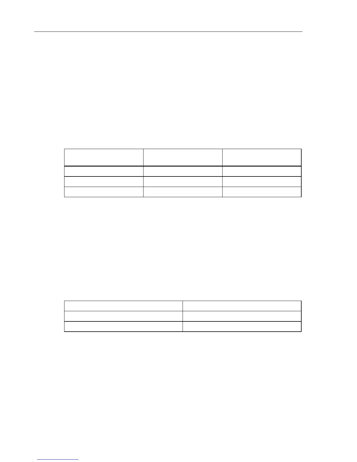
Table 4-13. Bandwidth Check of Voltage Channels A/L1, B/L2, C/L3
Voltage Channel to be verified Readout at 50 Hz (adjust
Calibrator with EDIT FIELD)
Readout at 3 kHz
A/L1 Fluke 435-II /437-II: 215 V Fluke 435-II /437-II: ≥ 204.2 V
B/L2 Fluke 435-II /437-II: 215 V Fluke 435-II /437-II: ≥ 204.2 V
C/L3 Fluke 435-II /437-II: 215 V Fluke 435-II /437-II: ≥ 204.2 V
9. Set the Calibrator to STBY.
Accuracy Check of Channel N (Neutral):
10. Connect the N input with the C/L3 input (See Figure 4-4). A/L1, B/L2, C/L3 now
give zero reading.
11. Set the Calibrator to 50 Hz / 400 V and then to OPR.
12. Check for a voltage readout V rms between 390.0 ... 410.0 V.
13. Check the 6 kV range according to the table below.
Table 4-14. Accuracy Check of Voltage Channel N (Neutral)
Set Calibrator to Readout at Voltage Channels N
400 V, 50 Hz, OPR 390.0 ... 410.0 V
1000 V, 50 Hz, OPR 990.0 ... 1010 V
14. Set the Calibrator to STBY.
Optional Test. Bandwidth Check of Channel N (*):
15. Set the Calibrator to 215 V, 50 Hz and OPR.
16. Now check the voltage channel N. Use the Calibrator’s field edit function
(AMPL/FREQ key) to adjust the Calibrator to an Analyzer readout of 400 V / 215 V.
 Loading...