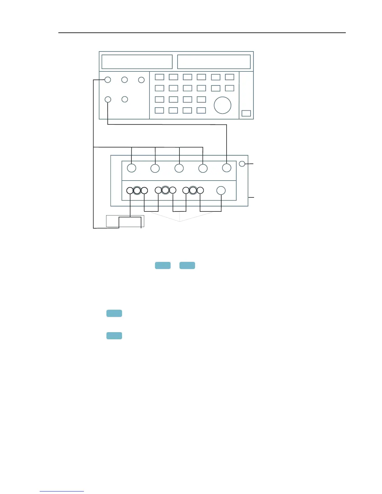
INPUT
BLOCK
LO
HI
NORMAL
PM 9093 PM 9093 PM 9093
PM 9082
RED
PM 9092
Figure 5-3. Offset, Low Voltage, and Current Gain Adjustment
2. The display must show step CL 0300.
If it does not, then press
F1
or
F2
to select the first calibration step in Table 5-
1.
3. Set the Calibrator output to source the signal 0 Hz, 0 V required for the calibration
steps in Table 5-1.
4. Set the Calibrator in operate (OPR) or standby (STBY) as indicated.
5. Press
F3
to start the calibration.
6. Wait until the display shows calibration status
:READY .
7. Press
F2
to select the next calibration step, and start the calibration.
Continue through all calibration points of Table 5-1.
8. When you are finished, set the Calibrator to Standby (STBY).
9. Continue at Section 5.6.3.
 Loading...