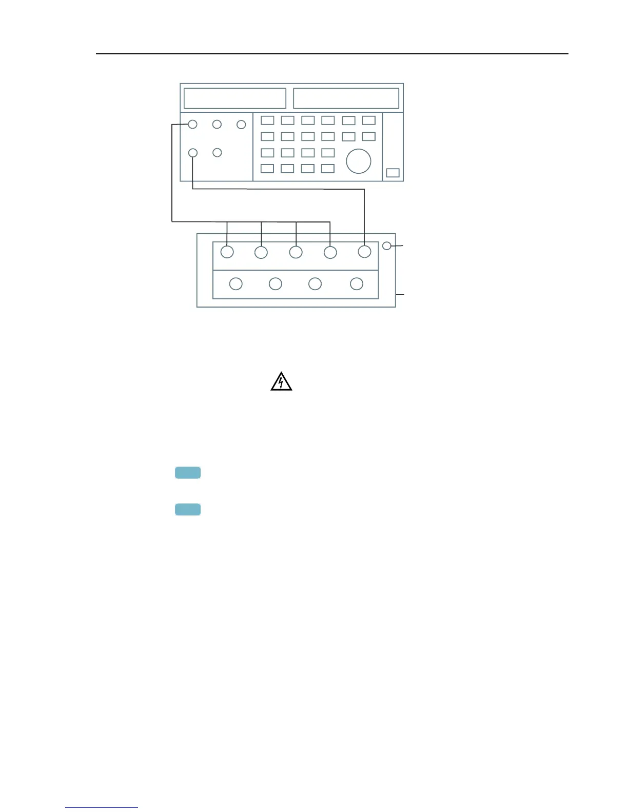
INPUT
BLOCK
LO
HI
NORMAL
Figure 5-4. Voltage Gain Adjustment
3. Set the Calibrator to supply 120 V, 50 Hz.
Warning
Dangerous voltages will be present on the calibration source
and connection cables during the following steps. Ensure that
the Calibrator is in standby (STBY) mode before making any
connection between the Calibrator and the Analyzer.
4. Set the Calibrator to operate (OPR).
5. Press
F3
to start the calibration.
6. Wait until the display shows calibration status
:READY.
7. Press
F2
to select the next calibration step, set the Calibrator to the next
calibration point, and start the calibration. Continue through all calibration points of
Table 5-2.
8. Set the Calibrator to STBY (Standby).
 Loading...