Appendices
Bushealth Measurements
A
A-3
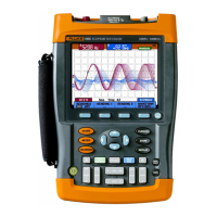
Connection between controller and devices is made using
a dedicated yellow flat cable as shown in the figure below
(cross section). Connection to the devices is done with
piercing connectors. To connect Probe Tip and Black
Ground Lead to + (brown conductor) and – (blue), the
TP88 Back Probe Pins (optional) can be used to probe
screw terminals at the end of the flat cable or as piercing
probes. The material of the flat cable also allows to pierce
the pin into it. After removal of the pin the material closes
again.
AS-i also uses M12-connectors for data as well as on/off
signals. The figure below shows where to find + and – on
such a connector.
1
+
: Input A
10:1
4
3 (-) : GND
2
5
M12 CONNECTOR
(FEMALE)
CAN Bus/DeviceNet.
The Controller Area Network (CAN) is used on board of
automobiles and also in industrial applications. The
industrial bussystem DeviceNet is based on CAN
hardware. CAN is a two-wire differential bus used to
control actuators and to read out sensors. The bus allows
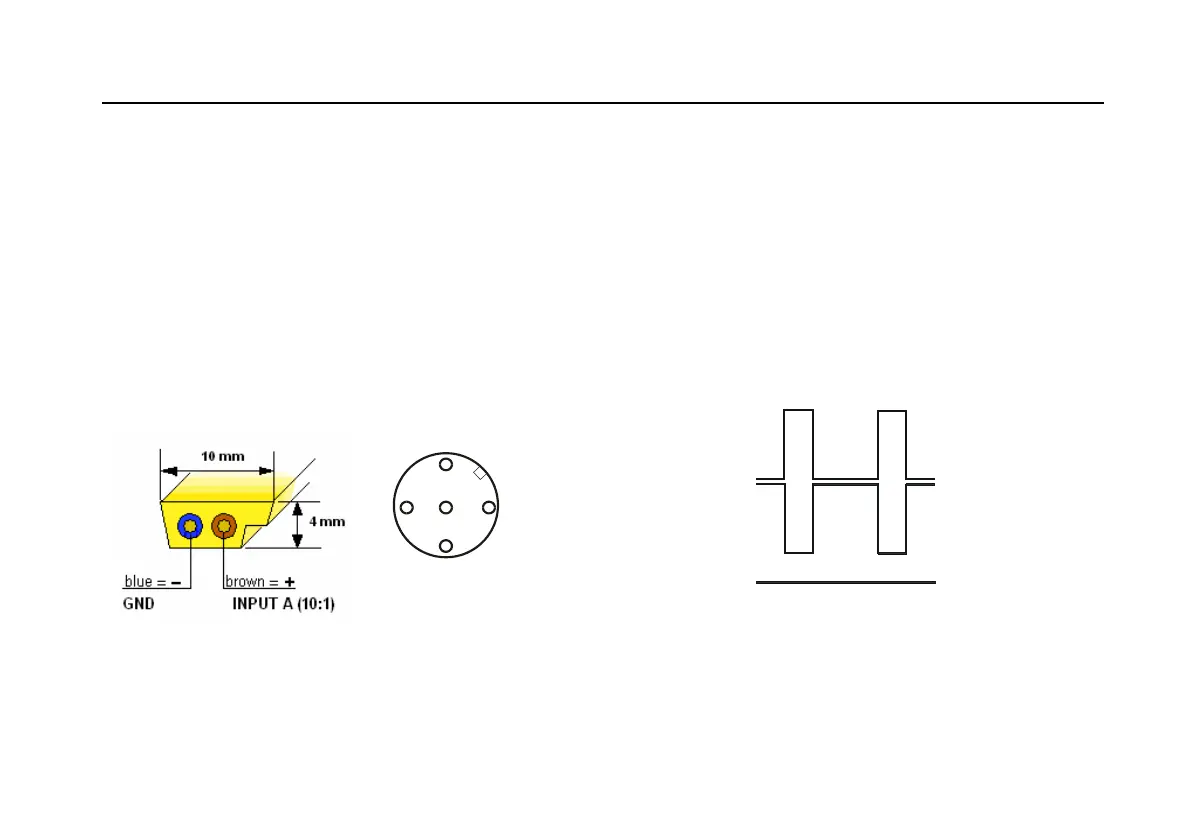
data exchange between different devices. The signal
behavior in time is shown in the figure below. The signal
wires are marked CAN_L and CAN_H. There is also a
common (reference wire) CAN_GND. Data traffic is
continuous.
CAN_H
CAN_L
CAN_GND
3.5 V
2.5 V
V
1.5 V
(probe tip B) +
(GND lead A)
(probe tip A)
(GND lead B)
To check CAN Bus, ScopeMeter Channel A and B are on
and DC coupled. The recommended probes are Fluke
10:1 probes.