45
Users Manual
3-4
Neither function modifiers (REL, dB, HOLD, and MN MX) nor the manual range mode
can be selected in the secondary display. Measurement ranges in the secondary display
are always selected through autoranging.
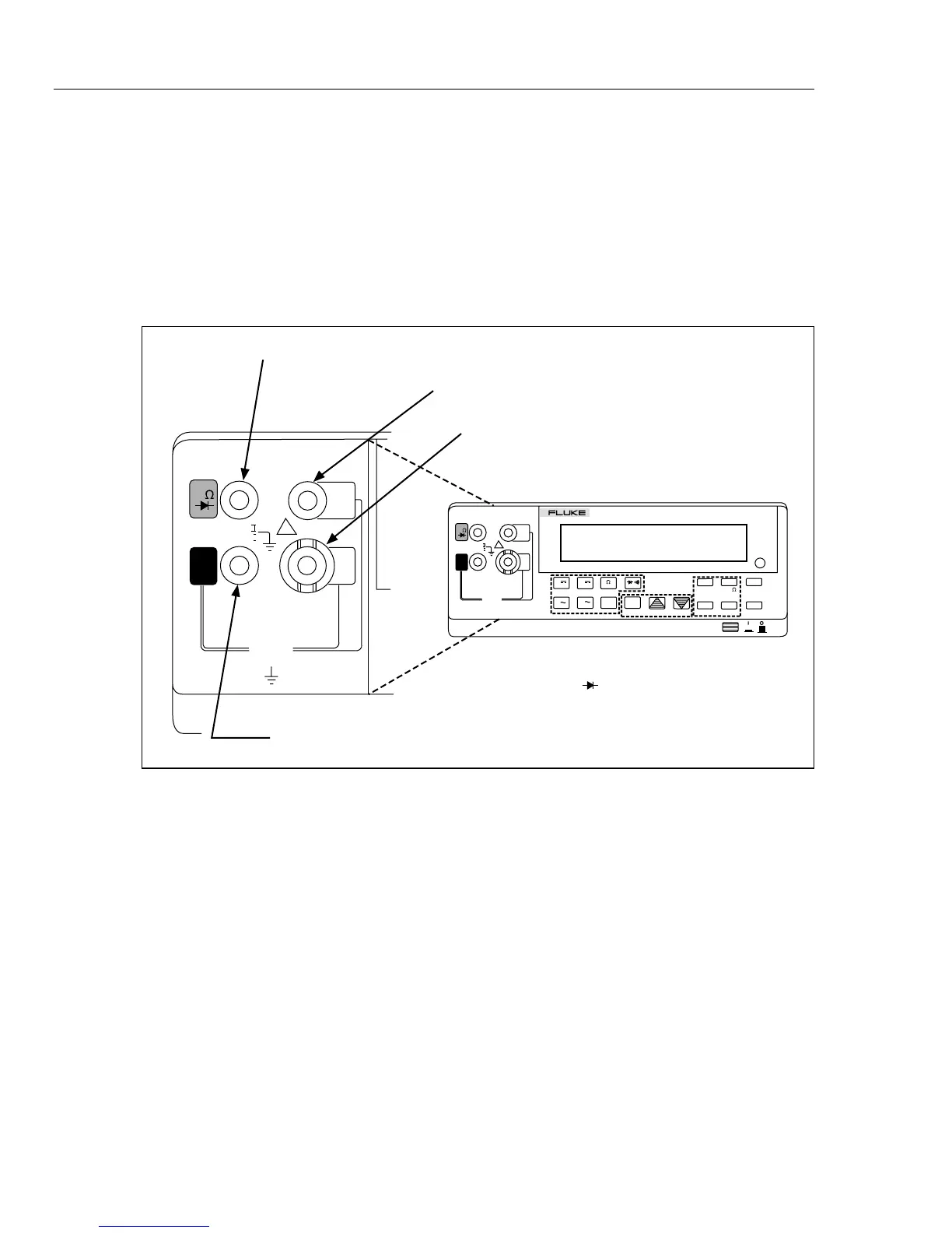
Input Terminals
The input terminals, shown in Figure 3-4, are located on the left of the front panel.
The meter is protected against overloads up to the limits shown in Table 3-1. Exceeding
these limits poses a hazard to both the meter and operator.
CAL
ENABLE
V
10A
100
mA
600V CAT I
1000V CAT I
FUSE F1
500 mA
F 250V
POWER
AUTO
2ND
MN MX
RATE
dB
REL
REF# LOCAL
THRESH ADDR BAUD
HOLD
LO
HI
COMP
A
A
V
FREQ
DUAL DISPLAY MULTIMETER
45
V
!
REF
FUSED
COM
V
10A
100
mA
600V CAT I
1000V CAT I
FUSE F1
500 mA
F 250V
!
FUSED
COM
Volts, Ohms, Diode Test Input Terminal
Amperes Input Terminal. For Current Measurements up to
10A continuous (or 20A for 30 sec).
Milliamperes Input Terminal. For Current Measurements
up to 100mA.
Common Terminal. Return Terminal for all Measurements.
Note: Frequency Measurements are Normally taken
from the V Input, although the 10A and
100mA Inputs can be used.
Ω
aam12f.eps
Figure 3-4. Input Terminals