-9.5
RTD/Thermocouple Calibrator
714B Performance Verification
Verify mV Measure
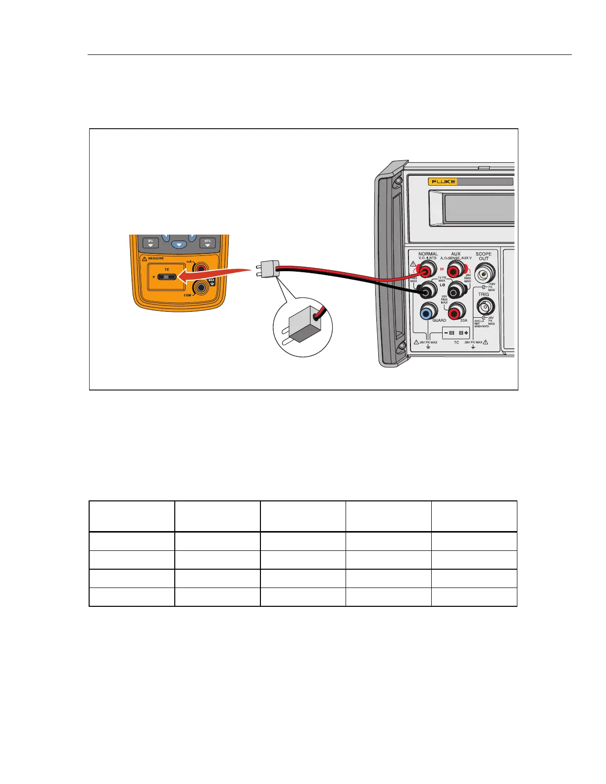
1. Make connections between the 714B and the 5522A with copper wire, as
shown in Figure 7.
Fluke 5522A
Fluke 714B
Pure Copper Cables
Pure Copper TC Miniplug
hwp007.eps
Figure 7. Verify 714B mV Measure
2. Push to set the 714B to mV Measure mode.
3. Set the 5522A to the first value in Table 9.
4. Output the mV values in Table 9 and verify that the 714B readings are within
the limits shown.
Table 9. 714B mV Measure Limits
1 Yr. Lower Limit 1 Yr Upper Limit 2 Yr. Lower Limit 2 Yr Upper Limit
Sourced (mV)
(mV) (mV) (mV) (mV)
-9.511 -9.489 -9.517 -9.483
10 9.989 10.012 9.983 10.017
40 39.984 40.016 39.977 40.023
69.980 70.020 69.971 70.029
Verify TC Measure (Type K)
1. Set the 714B to Type K Measure mode.
2. Set the 7526A to TC Out Type K.
3. Use K type TC sensor to connect the 7526A and the 714B, as shown in
Figure 8.
17
70

 Loading...