EasyManuals Logo

Fluke 9062 User Manual

Fluke 9062
22 pages
To Next Page IconTo Next Page
To Previous Page IconTo Previous Page
Page #9 background imageLoading...
Page #9 background image
Motor & Phase Rotation Indicator
Symbols
5
Symbols
The following symbols appear on the 9062 or in this manual.
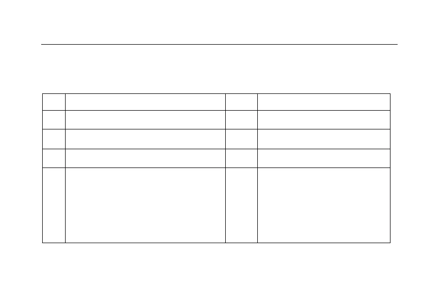
Table 1. Symbols
Y
Risk of electric shock
J
Earth
W
Risk of Danger. Important information.
See manual.
D
AC or DC
X
Hazardous voltage.
v=
Recycling information
T
Equipment protected by double or
reinforced Insulation
P
Conforms to EU directives.
M
Battery
CAT III
OVERVOLTAGE (Installation)
CATEGORY III, Pollution Degree
2 per IEC1010-1 refers to the level
of Impulse Withstand Voltage
protection provided. Equipment of
OVERVOLTAGE CATEGORY III
is equipment in fixed installations
(e.g., electricity meter and primary
over-current protection equipment.

Questions and Answers:

Question and Answer IconNeed help?

Do you have a question about the Fluke 9062 and is the answer not in the manual?

Fluke 9062 Specifications

General IconGeneral
Housing colorBlack, Yellow
Frequency range2 - 400 Hz
3 phase indicationYes
Operating altitude0 - 2000 m
Phase display range120 - 400 V
Operating voltage (max)400 V
Operating temperature (T-T)0 - 40 °C
Operating relative humidity (H-H)15 - 80 %
International Protection (IP) codeIP40
Battery voltage9 V
Number of batteries supported1
Weight and Dimensions IconWeight and Dimensions
Depth27 mm
Width61 mm
Height124 mm

Related product manuals