Model 787
Calibration Manual
14
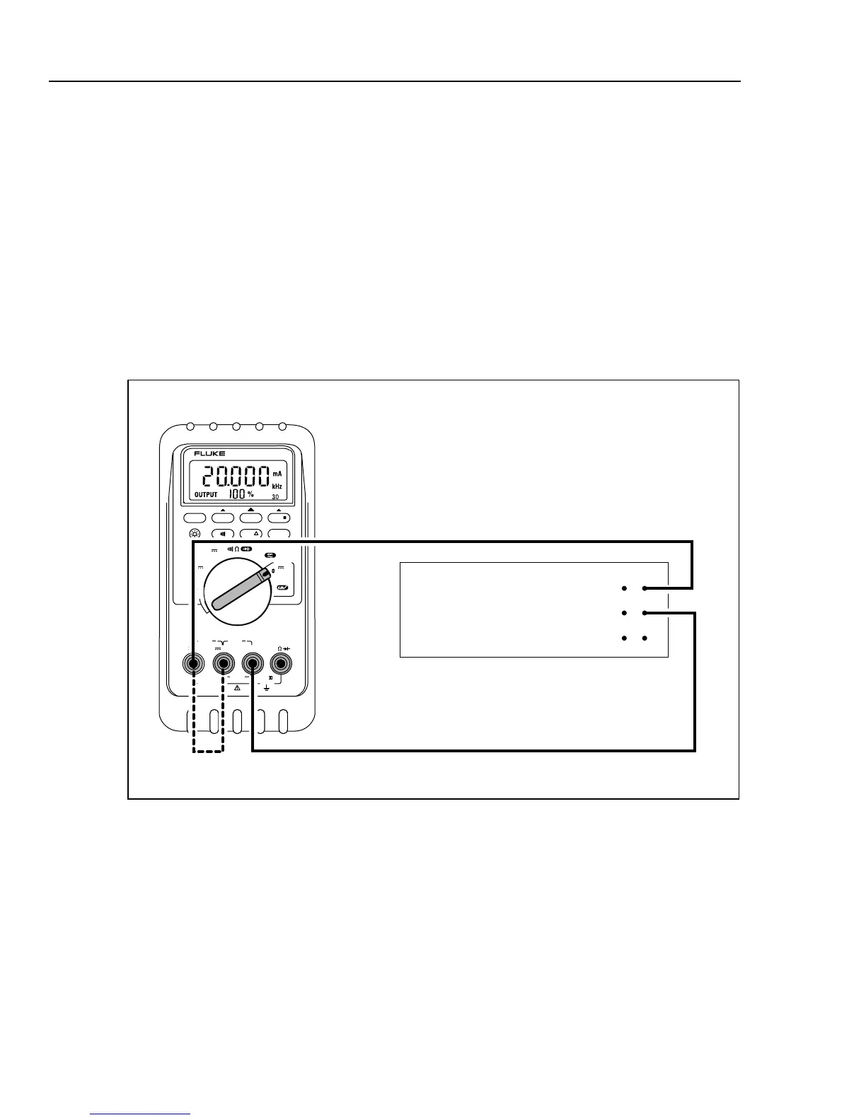
Loop Power Test
1. Make a short circuit connection between the SOURCE + (DA) and − (FmA)
terminals on the UUT.
2. Connect the voltage input terminals of the multimeter to the
SOURCE + and COM
terminals on the UUT as shown in Figure 3.
3. Put the multimeter in the dc volts (
L) autorange function.
4. Put the UUT rotary switch in the
OUTPUT mN position.
5. Use the
% STEP key to apply 20 mA from the UUT.
The multimeter display should read at least 12 V.
If the voltage displayed is less than 12 V, either the battery in the UUT is weak or
the current source power supply in the UUT is faulty.
OFF
A
mA
COM
V
1000V
30mA
FUSED
0.44A
(1A/30 sec)
FUSED
mA
mA
A
mA
OUTPUT 0-24mA
SOURCE SIMULATE
+ +
% STEP COARSE FINE
mV
V
V
OUTPUT
CAT
787
PROCESSMETER
MIN MAX RANGE HOLD
H
REL Hz
HP 3458A
DC Volts Autorange
Function
UUT
LT006F.EPS
Figure 3. Verifying Loop Power