Calibration Manual
Verification Tests
19
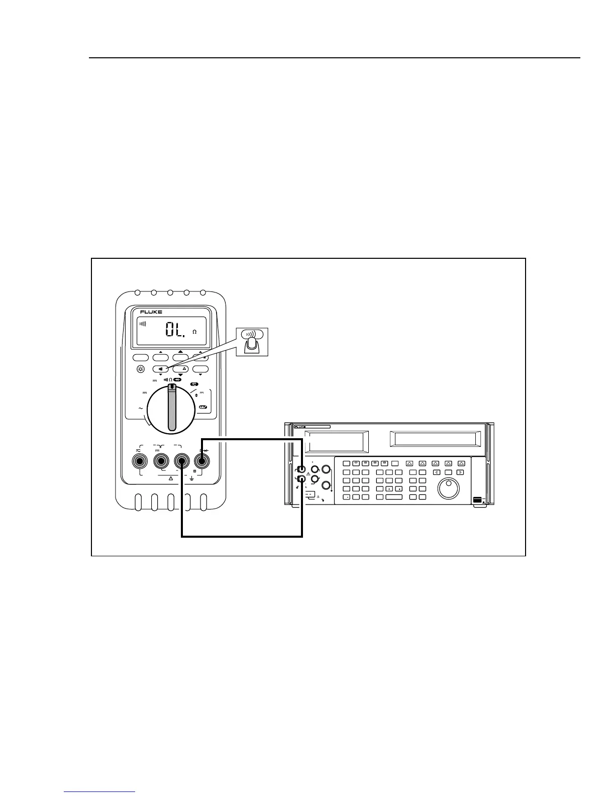
Checking the Continuity Test Function
1. Put the calibrator in Standby (STBY) mode, and put the UUT rotary switch in the e
position.
2. Connect the calibrator to the
COM and z terminals on the UUT as shown in
Figure 7.
3. Press
T (continuity beeper) on the UUT to select the continuity test.
4. Using the calibrator, apply a resistance output of 230 ± 20 Ω.
The beeper should stay off.
5. Using the calibrator, apply a resistance output of 120 ± 20 Ω.
The beeper should turn on.
OFF
A
mA
COM
V
1000V
30mA
FUSED
0.44A
(1A/30 sec)
FUSED
mA
mA
A
mA
OUTPUT 0-24mA
SOURCE SIMULATE
+ +
% STEP COARSE FINE
mV
V
V
OUTPUT
CAT
787
PROCESSMETER
MIN MAX RANGE HOLD
H
REL Hz
UUT
5500A
POWER
I
O
0•
123
456
789
ENTER
M
k
m
VHz
FIELD
EDIT
/
+
F
OPR EARTH SCOPE BOOST MENU
PREV
SHIFT
RESET
CE
SETUP
REF
NEW
TC
MEAS
¡F
µ
n
p
W
dBm sec
¡CA
MULT
x
DIV
÷
OUT
TRIG
5500A
CALIBRATOR
20V PK
MAX
HI
LO
TC
TRIG
OUT
1000V
RMS
MAX
20V
RMS
MAX
1V PK
MAX
20V PK
MAX
NORMAL AUX
SCOPE
V, ,
RTD
A, -SENSE,
AUX V
200V PK
MAX
STBY
LT0008F.EPS
Figure 7. Continuity Test Connections