ProcessMeter™
Performance Verification
17
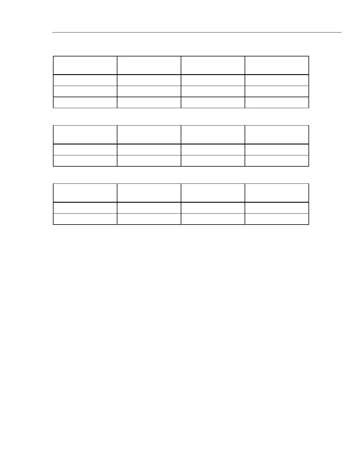
Table 5. DC mA Test
789 Range
Calibrator
DC Current
Minimum Acceptable
Reading
Maximum Acceptable
Reading
No Range Switching 4.000 mA 3.996 mA 4.004 mA
No Range Switching 12.000 mA 11.992 mA 12.008 mA
No Range Switching 20.000 mA 19.988 mA 20.012 mA
Table 6. DC Amp Test
789 Range
Calibrator
DC Current
Minimum Acceptable
Reading
Maximum Acceptable
Reading
No Range Switching 0.100 A 0.098 A 0.102 A
No Range Switching 0.400 A 0.397 A 0.403 A
Table 7. AC Amp Test
789 Range
Calibrator AC Current
and Frequency
Minimum Acceptable
Reading
Maximum Acceptable
Reading
No Range Switching 0.100 A @ 60 Hz 0.097 A 0.103 A
No Range Switching 0.400 A @ 60 Hz 0.394 A 0.406 A
Diode Function Test
1. Put the calibrator in Standby (STBY) mode.
2. Turn the UUT rotary switch in the Vposition.
3. Press J (BLUE) to select diode test ().
4. Connect the calibrator to the COM and
terminals on the UUT as shown in
Figure 5.
5. Apply 2.0 V dc from the calibrator.
6. The UUT should read between 1.959 V and 2.041 V.
7. Put the calibrator in Standby (STBY) mode; then disconnect the calibrator from the
UUT.
8. Put the multimeter in the dc mA (autorange) function.
9. Connect the current terminals of the multimeter to the COM and
terminals on the
UUT.
The multimeter should read close to 0.3 mA. (There is no tolerance specification for
this current. This test just makes sure that the diode test current source is operating.)