ProcessMeter™
Performance Verification
19
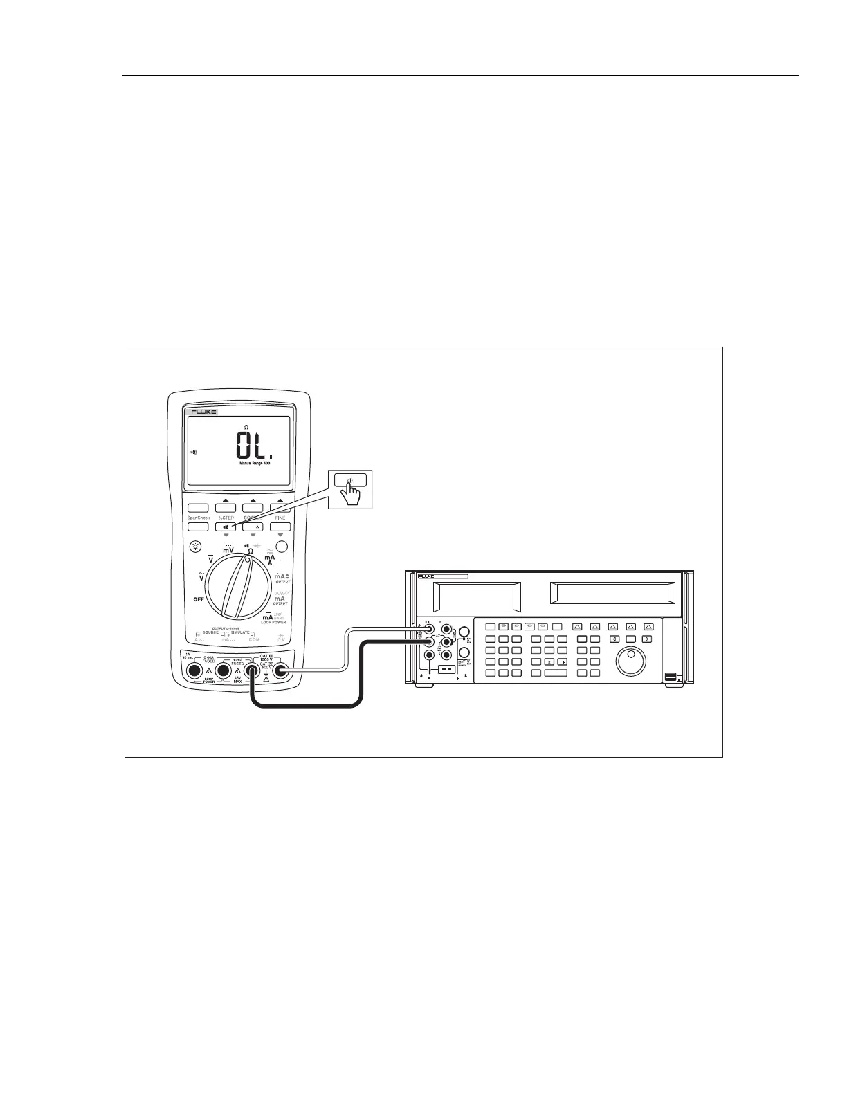
Continuity Function Test
1. Put the calibrator in Standby (STBY) mode, and turn the UUT rotary switch to the
V position.
2. Connect the calibrator to the COM and
terminals on the UUT as shown in
Figure 6.
3. Press G (continuity beeper) on the UUT to select the continuity test.
4. Using the calibrator, apply a resistance output of 260 ±20 Ω. The beeper should stay
off.
5. Using the calibrator, apply a resistance output of 100 ±10 Ω. The beeper should turn
on.
POWER
I
O
0•
123
456
7 8 9
ENTER
M
k
m
V Hz
FIELD
EDIT
/
+
F
OPR EARTH EXGRD SCOPE MENU
PREV
SHIFT
RESET
CE
SETUP
REF
NEW
TC
MEAS
¡F
µ
n
p
W
dBm sec
¡CA
MULT
x
DIV
÷
MODES
MORE
STBY
HI
LO
TRIG
GUARD
TC
20A
NORMAL AUX
5520A CALIBRATOR
SCOPE
OUT
V, , ,
RTD
A, -SENSE,
AUX V
20V PK MAX
20V PK MAX
5522A
0%
RANGE HOLD
REL
MIN MAX
Hz
100%
789
PROCESSMETER
adm008F.EPS
Figure 6. Continuity Test Connections