789/787B
Calibration Manual
20
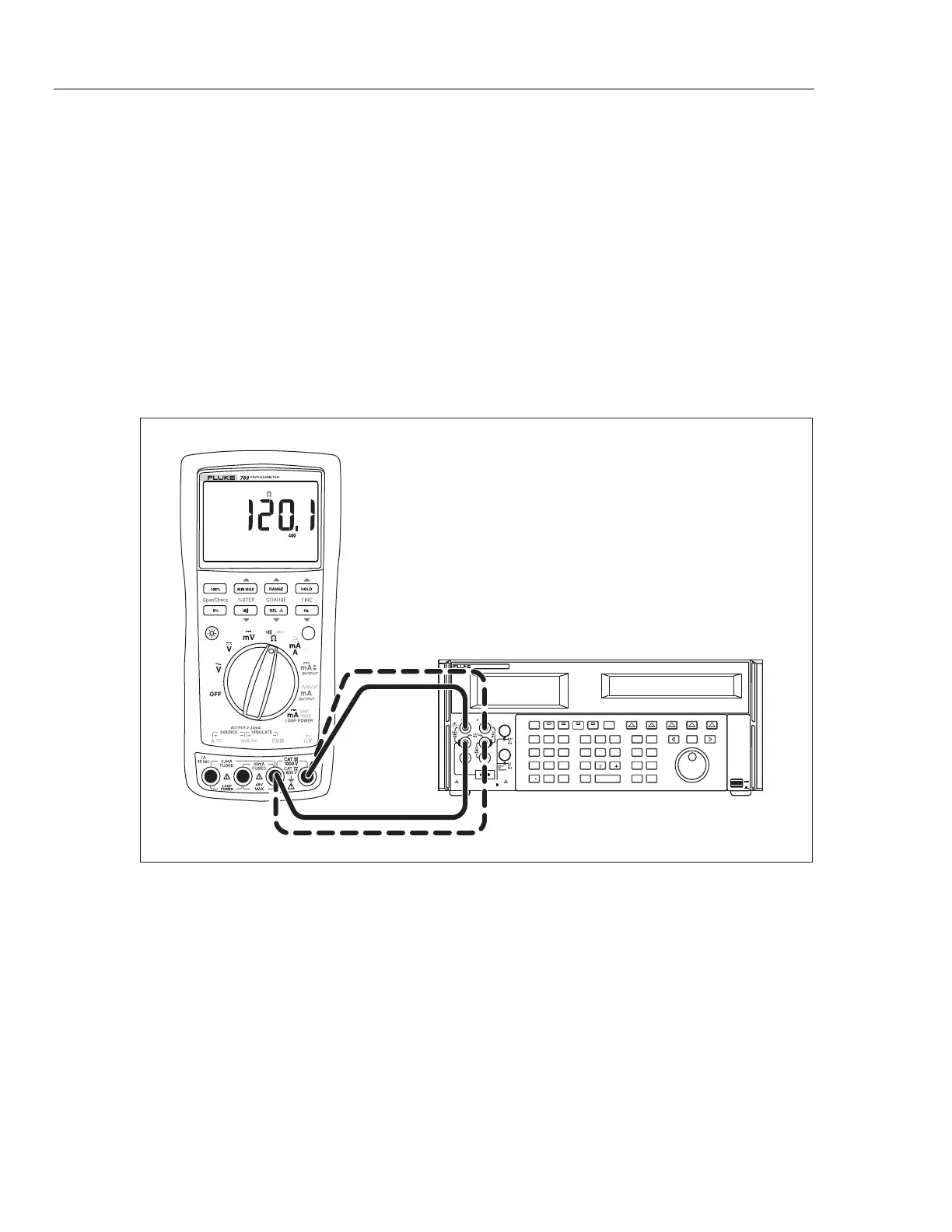
Resistance Measurement Test
1. Put the calibrator in Standby (STBY) mode.
2. Put the UUT rotary switch in the
V position.
3. Connect the OUTPUT and SENSE leads of the calibrator to the UUT as shown by
the solid and dotted lines in Figure 7.
4. Apply the calibrator resistance values in Table 8 in the UUT 400 Ω to 40 kΩ range.
Compare the readings on the UUT to the acceptable readings shown.
5. Change the connections to the UUT. Using the Fluke 5440A-7002 low thermal leads,
connect the calibrator to the UUT as shown by the solid lines in Figure 7.
6. Apply the rest of the calibrator resistance values in Table 8 (400 kΩ range and
above). Compare the readings on the UUT to the acceptable readings shown.
POWER
I
O
0•
123
456
7 8 9
ENTER
M
k
m
V Hz
FIELD
EDIT
/
+
F
OPR EARTH EXGRD SCOPE MENU
PREV
SHIFT
RESET
CE
SETUP
REF
NEW
TC
MEAS
¡F
µ
n
p
W
dBm sec
¡CA
MULT
x
DIV
÷
MODES
MORE
STBY
HI
LO
TRIG
GUARD
TC
20A
NORMAL AUX
5520A CALIBRATOR
SCOPE
OUT
V, , ,
RTD
A, -SENSE,
AUX V
20V PK MAX
20V PK MAX
5522A
UUT
adm004F.EPS
Figure 7. Resistance Measurement Test Connections