Positio
n
Part Description
13 Thermal contact/
Thermistors
For information about the thermal contact and thermistors, see Monitoring equipment
(page 14).
14 Support bearing Consisting of a two-row ball bearing
Monitoring equipment
The following applies to the monitoring equipment of the pump:
• The stator incorporates three thermal contacts connected in series that activate the
alarm and stops the pump at overtemperature
• The thermal contacts open at 140°C (285°F).
• Ex-approved pumps must have thermal contacts connected to the control panel.
• The sensors must be connected to either the MiniCAS II monitoring equipment or an
equivalent equipment.
• The monitoring equipment must be of a design that makes automatic restart
impossible.
• The pump is supplied with an inspection sensor FLS 10 for sensing the presence of any
liquid in the inspection chamber.
• Information in the junction box shows if the pump is equipped with optional sensors.
Optional sensors
Thermistor Thermistors are optional sensors for measuring the temperature. They are
connected in series in the stator and activate the alarm at overtemperature.
Thermistors are not applicable to Ex-approved pumps.
NOTICE:
Thermistor must never be exposed to voltages higher than 2.5 V. If the
voltage exceeds this value, for example when the control circuit is tested, the
thermistors will be destroyed.
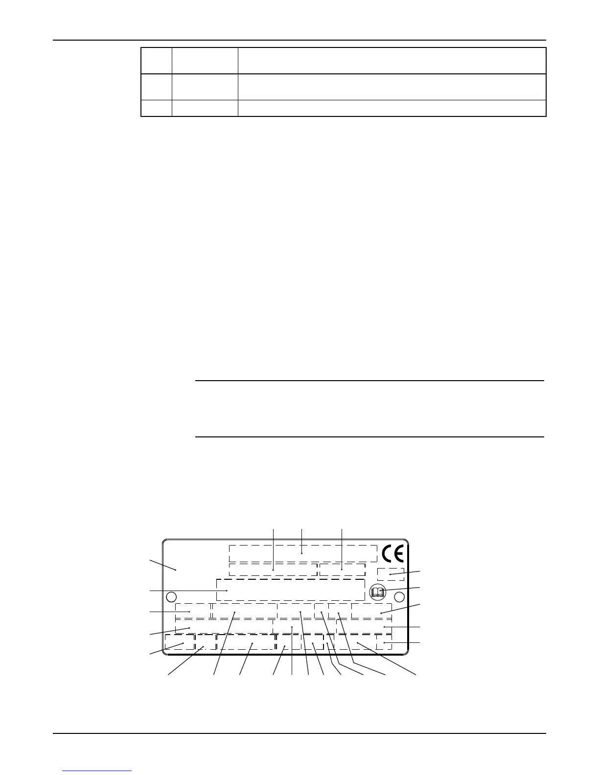
The data plate
The data plate is a metal label located on the main body of the products. The data plate
lists key product specifications. Specially approved products also have an approval plate.
2
1312 14
22
21
20
17 18 1916159 10 11
8
7
6
5
4
3
1
23
24
WS006257A
1. Curve code/Propeller code
2.
Serial number, see Product denomination (page 17)
3. Product number
Product Description
14 Flygt 3153 Installation, Operation, and Maintenance Manual