6
Hardware Features
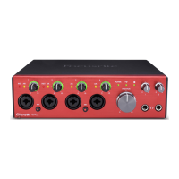
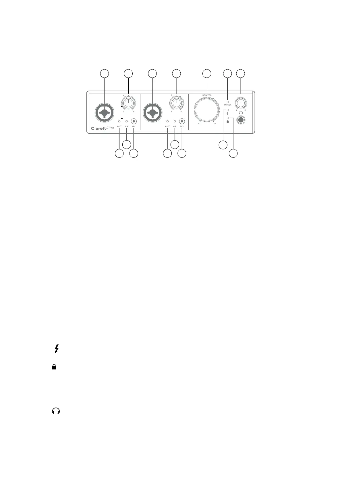
Front Panel
24
5 5
4 2
6
7
1 3 3 8 9101
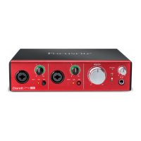
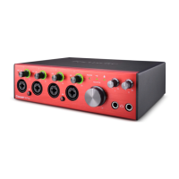
The front panel includes all the input gain and monitoring controls as well as two of the input
connectors for Mic, Line and Instrument signals.
1. INPUTS 1 & 2 – “Combo XLR” input sockets for each channel - connect microphones, instruments
(e.g., guitar), or line level signals via XLR or ¼” jacks as appropriate. Either TRS (balanced) or
TS (unbalanced) jack plugs can be used for instruments or line level signals.
2. 48V – two switches enabling 48 V phantom power at the XLR contacts of the combo connectors
for mic inputs 1 and 2 respectively. The switches each have an associated red LED indicating
phantom power is selected.
3. Gain 1 and 2 – two rotary controls: adjust the input gain for the signals at Inputs 1 and 2
respectively. The gain controls have concentric bi-colour LED ‘halos’ to conrm signal level:
green indicates an input level of at least -24 dBFS (i.e., ‘signal present’), the ring then turns
red when signal level reaches 0 dBFS.
4. INST – two red LEDs which illuminate when INST mode is selected for the jack contacts of
Inputs 1 or 2 from Focusrite Control software. When INST is selected, the gain range and input
impedance are altered (relative to LINE), and the input is made unbalanced. This optimises
it for the direct connection of instruments via a 2-pole (TS) jack plug. When INST is off, the
inputs are suitable for the connection of line level signals. Line level signals may be connected
either in balanced form via a 3-pole (TRS) jack or unbalanced, via a 2-pole (TS) jack.
5. AIR – two yellow LEDs which illuminate when the AIR function is selected for each input
from Focusrite Control. AIR modies the frequency response of the input stage to model the
classic, transformer-based Focusrite ISA mic preamps.
6.
(Thunderbolt active) – a green LED which illuminates when the unit has established a
connection with the computer to which it is connected.
7.
(Locked) – a green LED which conrms clock synchronisation, either to the Clarett 8Pre’s
internal clock or to an external digital input.
8. MONITOR – main monitor output level control – this control will normally control the level
at the main monitor outputs on the rear panel, but can be congured in Focusrite Control to
adjust the level of any of the unit’s four analogue outputs.
9.
(Headphones) – connect a pair of stereo headphones at the ¼” TRS jack socket below
the control. The headphone output always carries the signals currently routed to analogue
outputs 3 and 4 (as a stereo pair) in Focusrite Control.
10. POWER – green LED conrming DC power is connected.