56
Next Generation Diagnostic Platform NT726TS User's Manual V1.0
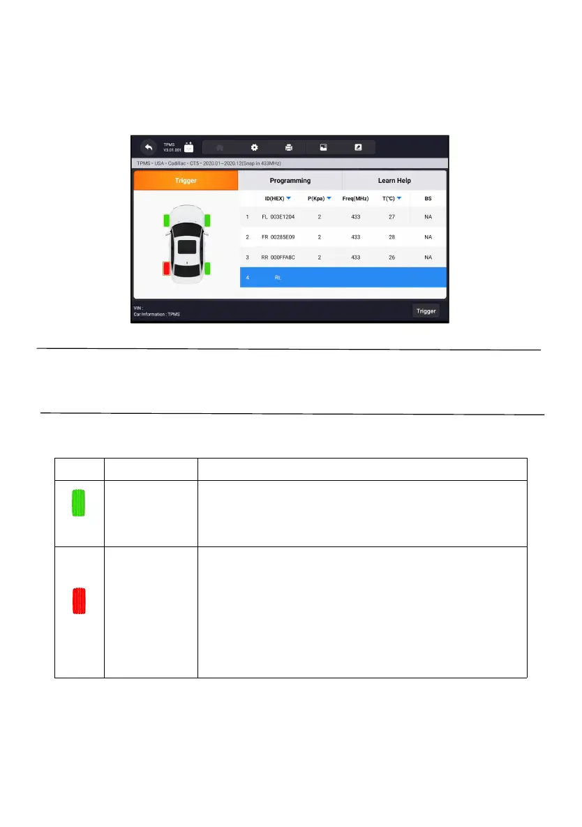
sidewall near the valve stem, and then press the Trigger button. The
Display Tablet will send low frequency signal to trigger the sensor.
3. The sensor data of the selected wheel will display on the table of the
screen once the sensor is successfully activated and decoded.
Figure 11-4 Sample Trigger TPMS Screen
NOTE:
The Display Tablet will perform TPMS check in a sequence of FL (front left),
FR (front right), RR (rear right), RL (rear left) and SP (spare, if any).
4. Wheel with a feedback icon, red or green vertical rectangle, indicates
sensor trigger has been finished. Refer to Table 11-1 for details.
Sensor activated
successful
TPMS sensor is successfully activated and decoded. The table on
the right side of the screen displays the sensor information.
If the search period expires and no sensor is activated or decoded,
the sensor may be mounted incorrectly or cannot function. The table
on the right side of the screen displays “Failed”.
If as sensor with a duplicate ID has been read, the screen displays a
message “Sensor ID duplicated”.
In the case, repeat the test procedure.
Figure 11-5 Possible results for triggering
11.2 Programming Operations
The programming function is used to program the sensor data to the Foxwell
sensor T10 and replace the faulty senor (poor battery life or malfunction). The