PRIMO Instruction Manual
23
person in order to prevent any risk.
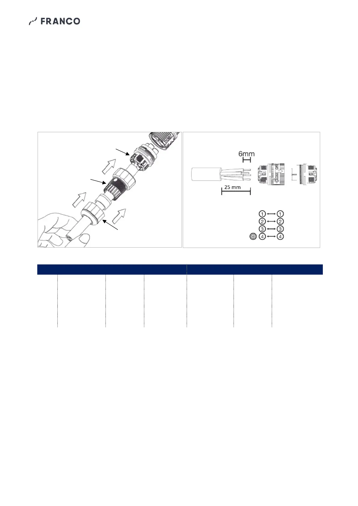
The machine is equipped with three IP68 male
connectors pre-wired on the internal cables of
the fan, pump and drain valve. Also supplied
(already connected to the male connector on
the machine) are the corresponding female
connectors for connecting the external power
cables of the fan, pump and exhaust valve (Fig.
5.2.1):
- Feed the power cables through the plate
with cable glands.
- Unscrew the threaded ring nut and the cable
gland of the female connector.
- Pass the cable through the ferrule and cable
gland.
- Strip the internal conductors (Fig. 5.2.2) and
insert them into the connector terminals as
shown in the table below. The connector
pins are numbered 1 to 4.
- Tighten terminal screws.
- Reassemble the connector and check that
all parts are tightly screwed together to
ensure the correct degree of protection.
Fig. 5.2.1 Fig. 5.2.2