WLA300 Rev170606
38
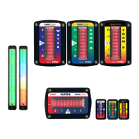
Typical System Conguration WLA3XX
Figure 17. Typical System Conguration WLA3XXX
Primary
Display
Pressure Sensor
Remote
Display
MaxVision
LED
Display
Cab
Miniature
Display
Warning
Buzzer
12/24 VDC
9-30VDC
9-30VDC
Power
Terminating
Resistor
To Remote
Light Driver
To Other
Miniature
Displays
Datalink Daisy
Chain To Other
Devices
FRC Datalink
9-30VDC
Note: See Pin Description/
Location on pages 32 and 34.
Terminating
Resistor
Note: Multiple number of remote displays can be
connected to the primary display. Any remote display can
become a primary by disconnecting the sensor from the
primary and connecting it to the remote.
White
Wire
Pin 6
 Loading...