•
Ensure chamber piston rods are in line
with the slack adjusters.
Wheel and Tire Inspection
Walk around the vehicle and visually inspect each
wheel and tire assembly.
IMPORTANT: Wheel covers decrease drag force
as a vehicle moves, thereby improving fuel effi-
ciency. If replacement of a wheel cover is nec-
essary, the replacement cover must meet or ex-
ceed the drag reduction performance of the
originally installed cover in order to maintain
compliance with greenhouse gas and full effi-
ciency regulations (GHG14).
1.
If the vehicle was originally equipped with wheel
covers, ensure all wheel covers are present. In-
spect wheel covers for damage or wear. Remove
wheel covers from rear drive wheels, if equipped,
prior to inspecting the tires and wheel compo-
nents.
NOTE: During wheel cover installation, ensure
the V-notch in the liner inner retaining ring is
centered on the valve stem. The inner and outer
retaining rings should be uniformly aligned to
each other and to the wheel rim. The outer re-
taining ring of the liner is equipped with two
canvas flaps. When installing the face cover,
make sure the cover retaining ring is inserted
between the two canvas flaps on the liner outer
retaining ring so that the Velcro strips line up
10/11/2005 f421397
1
2
3
4
5
6
7
8
9
A
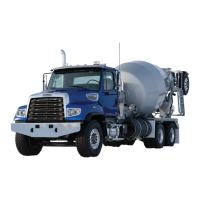
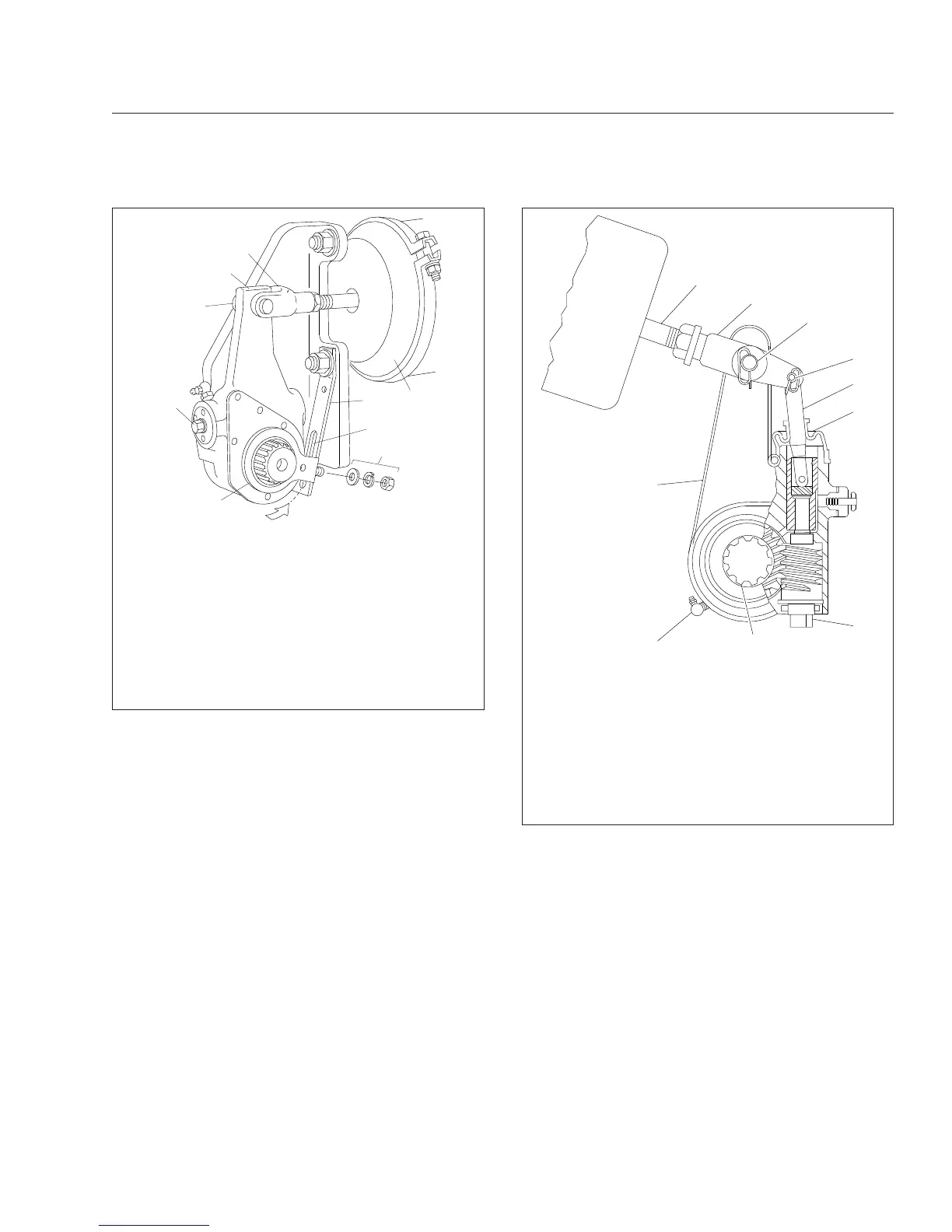
A. Rotate the control arm toward the brake chamber
until you can feel it contacting the internal stop.
1. Clevis
2. Slack Adjuster
3. Clevis Pin
4. Manual Adjusting Nut
5. Control Arm
6. Control-Arm Washers and Nut
7. Anchor Strap Slot
8. Anchor Strap
9. Brake Chamber
Fig. 21.2, Haldex Automatic Slack Adjuster
01/31/2011 f422530
1
2
3
4
5
6
7
8
9
10
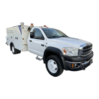
1. Grease Fitting (if equipped)
2. Slack Adjuster Housing
3. Brake Chamber Pushrod
4. Clevis
5. Clevis Pin (large)
6. Clevis Pin (small)
7. Actuator Rod
8. Boot
9. Manual Adjusting Nut
10. Camshaft Splines
Fig. 21.3, Meritor Automatic Slack Adjuster
Pre- and Post-Trip Inspections and Maintenance
21.2