Instrumentation Control Unit
The instrumentation control unit (ICU) provides the
driver with engine and vehicle information. It is com-
prised of standard and optional gauges, an audible
warning, a driver message center, and a lightbar con-
taining warning and indicator lamps (also known as
telltales). Warning and indicator lamps illuminate in
red (danger), amber (caution), green (status advi-
sory), or blue (high-beam headlights active).
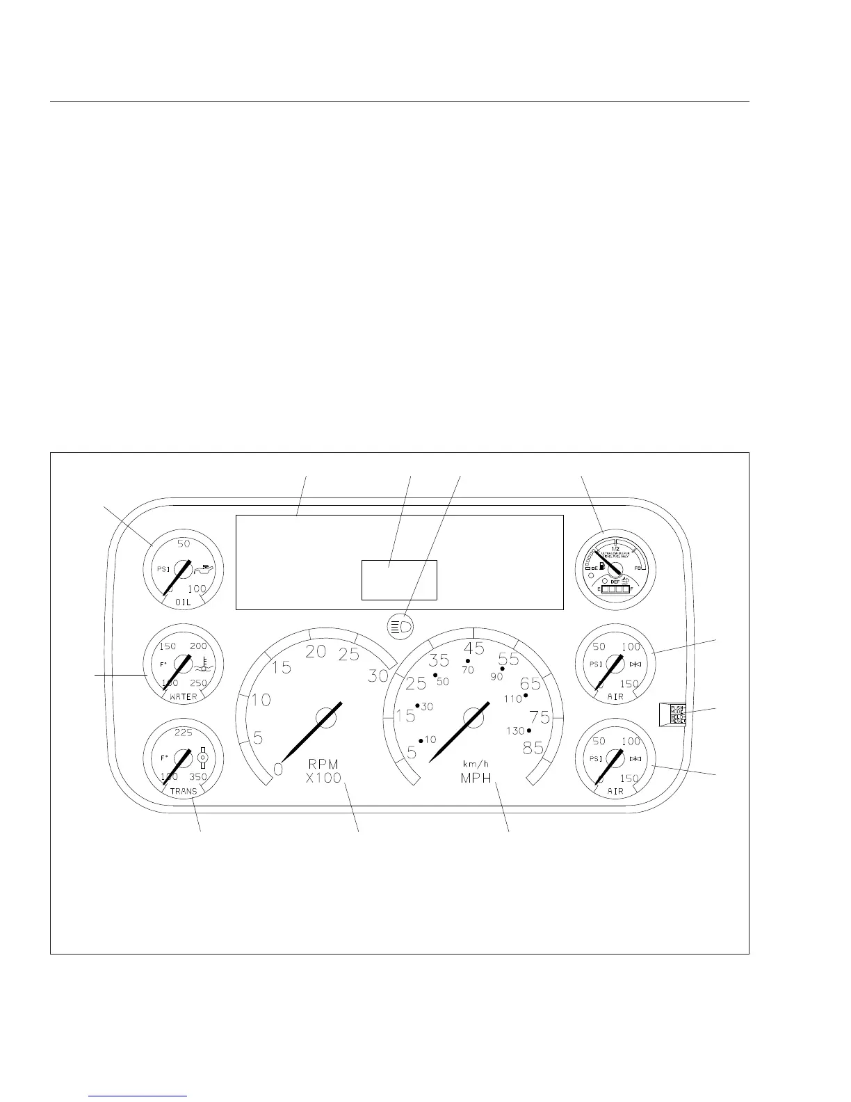
Figure 4.1 shows a typical ICU3 instrument cluster.
The following headings in this chapter provide addi-
tional information and operating instructions for ICU
components:
•
"Warning and Indicator Lights"
•
"Instruments"
•
"Driver Message Center"
Ignition Sequence
When the ignition is turned on, the ICU runs a self-
check. See Fig. 4.2. Observing the ignition sequence
is a good way to ensure the ICU is functioning
properly.
IMPORTANT: Do not crank the engine until the
ICU self-check is complete.
When the ignition is turned on, the following actions
should occur:
f610525a
1
234 5
6
7
8
12
11 10 9
09/10/2009
NOTE: This instrument cluster is shown with the U.S. speedometer, which shows miles per hour (mph) more prominently
than kilometers per hour (km/h).
1. Engine Oil Pressure Gauge
2. Lightbar
3. Driver Message Center
4. Headlight High-Beam Indicator
5. Fuel/DEF Level Gauge
6. Primary Air Pressure Gauge
7. Mode/Reset Button
8. Secondary Air Pressure Gauge
9. Speedometer (U.S. version)
10. Tachometer
11. Transmission Temperature Gauge
12. Coolant Temperature Gauge
Fig. 4.1, Typical ICU3 (U.S. shown)
Instruments
4.1