2.1
If not previously drained, drain the air res-
ervoirs using moderate brake applications
until pressure in both reservoirs is less
than 70 psi (483 kPa).
2.2
Turn the ignition to the ON position. The
ICU will complete a full gauge sweep and
bulb check, and the warning buzzer will
sound. Ensure the BRAKE AIR lamp re-
mains illuminated and the warning buzzer
continues to sound after the gauge sweep
is complete.
3.
Check air governor cut-in and cut-out pressures.
3.1
Start the engine and ensure the BRAKE
AIR lamp goes out and the buzzer si-
lences when pressure reaches approxi-
mately 70 psi (483 kPa) in both air reser-
voirs.
The air governor should cut out at ap-
proximately 120 psi (827 kPa). For ve-
hicles with an optional dryer reservoir
module (DRM), the cut-out pressure is
approximately 130 psi (896 kPa).
3.2
With the engine idling, apply the brake
pedal several times. The air governor
should cut in when pressure in the primary
air reservoir (top air gauge) reaches ap-
proximately 100 psi (689 kPa).
4.
Check air pressure build-up time.
4.1
With the air system fully charged, make
one full brake application and note the air
pressure reading on the primary air
gauge.
4.2
Further reduce air pressure using moder-
ate brake applications, then run the en-
gine at governed rpm.
4.3
Note the time that the pressure reaches
the previously noted reading on the pri-
mary air gauge, then note the time that
the air pressure reaches cut-out pressure.
4.4
If it takes longer than 30 seconds to reach
cut-out pressure after the primary air
gauge passes the previously noted pres-
sure (noted after one full brake applica-
tion), eliminate any leaks or replace the air
compressor before operating the vehicle.
5.
Check air leakage in the system.
5.1
With the parking brake applied, the trans-
mission out of gear, and the air system
fully charged, release the service brakes
and shut down the engine.
5.2
Wait one minute and note the air pressure
drop in psi (kPa) per minute from the pri-
mary air reservoir.
If the pressure drop exceeds the limits
shown in
Table 21.1, eliminate any leaks
before operating the vehicle.
6.
Check the air pressure reserve.
11/24/2010 f545704
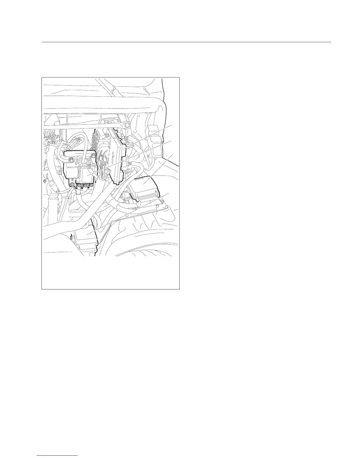
1
2
3
4
1. Bulkhead Module
2. Powernet Distribution Box (PNDB)
3. Main Power Distribution Module (PDM)
4. Powertrain PDM (PTPDM)
Fig. 21.7, Visible Engine Wiring
Pre- and Post-Trip Inspections and Maintenance
21.6