RWB II PLUS MICROPROCESSOR CONTROL
OPERATION
S70-200 OM
Page 13
COMMUNICATIONS TROUBLESHOOTING
Troubleshooting the communications:
Go to the FIXED SETPOINTS PAGE by using the “CHANGE”
key and the “ * ” key. The display will appear as:
FIXED SETPOINTS DISPLAY *
FIXED SETPOINTS: HIGH STAGE PRELUBE
COMM ACTIVITY—[ ] OIL PUMP PGM/A
Hi Disch Cut----[212F]
Hi Disch Alarm--[194F] Liq Inj Con 113F
Hi Oil Temp Cut-[167F] Filter------[25]
Hi Oil Temp Alarm[158F]Oil Heater[113F]
Lo Oil Temp Cut--[49F] Lo Oil Cut-[030]
Lo Oil Temp Alarm[58F] Lo Oil Alrm[025]
If the microprocessor is receiving information in the com-
munications port from the other compressor, a “2” will flash
between the brackets. During normal operation a “2” will flash
every 5 seconds.
At the same time information is display on the lower right
hand corner of the Auto Cycle display concerning the lead-
lag information:
AUTO CYCLE DISPLAY *
AUTO CYCLE Tue 04-10-90 08:44:57
DISPLAY: Press F1 To Exit
Suction Pressure--------[06.5 g ]
Comp Start - [99.0 g } Timer—[00 min]
Comp Stop— [29.0 hg] Timer—[00 min]
Min SV———[50%] Lead—[YES]
Active———[No ] 0111 111
This information is either “0” or “1” and represents what is
being sent from the other compressor. Consult Frick Com-
pany if additional information is required.
HOW THE MICROPROCESSOR WORKS
- SUMMARY -
The Frick microprocessor has 4 major components and a
variety of sensors. The major components are the SBC
(single board computer), two display screens, and the key-
board.
The SBC can be considered the brain of the microproces-
sor control console. The SBC contains the logic center which
provides the rules by which the microprocessor will oper-
ate, the integrated circuit chips which store the burned-in
memory of how the compressor unit is to behave, an analog
input to convert VDC from the various sensors into com-
puter binary language, and RAM (random access memory)
integrated circuit chips to store information which can be
readily changed by the microprocessor or, as in the case of
adjustable setpoints, by the operator. The SBC collects in-
formation, processes the information, and delivers instruc-
tions to the displays and to the output modules.
The SBC gathers information from several sources on the
compressor unit. Pressure transducers sense changes in
pressure and return a variable DC voltage of 1 to 5 VDC to
the SBC. The signals are converted into binary code which
the microprocessor understands. The microprocessor scans
the incoming data many times per second and compares
the information it receives with the instructions programmed
in the PROM chips, information stored in the RAM chips,
and instructions it has received from the console keyboard.
As operating conditions change, the microprocessor also
forwards the information it is receiving to the display screen.
When an operating condition or conditions develop which
the microprocessor program identifies as requiring a spe-
cific action, the microprocessor generates an instruction
which is forwarded to the output modules. The instruction
triggers a solid state output device capable of handling con-
trol voltage and the instruction is executed. In some cases,
such as load and unload instructions, the computer displays
the instruction on the Operating display with an L (load) or U
(unload) symbol at the same time as the appropriate output
is energized.
If the microprocessor receives information that indicates an
abnormal operating condition has been reached or is
present, it will generate one or more of the following instruc-
tions:
1. If a subsystem on the compressor unit, such as the oil
heater(s) or liquid injection, can correct the problem, the
microprocessor will energize or deenergize this system.
2. If a prealarm setpoint has been reached the micro-
processor will trigger the prealarm and display this informa-
tion on the Operating display and the Annunciator display.
3. If a cutout setpoint has been reached, the microproces-
sor will shut down the compressor. The microprocessor will
indicate CUTOUT on the Operating display and the infor-
mation present on the Operating display at the moment of
cutout will be stored and can be retrieved by rotating dis-
plays to the Freeze display. Additional information will be
available through the Annunciator and Shutdown Record
displays.
* Display for illustrative purposes only.
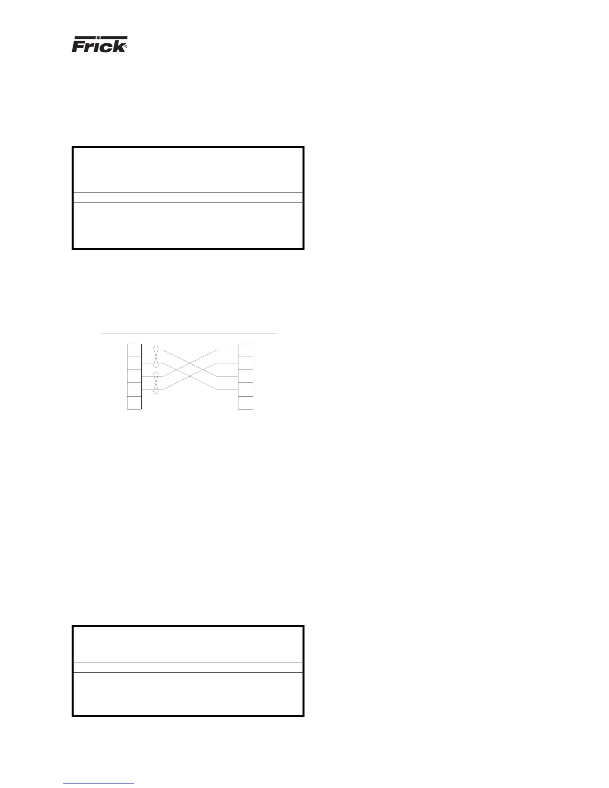
ARE ON THE SAME SKID
WIRED AT FRICK IF BOTH UNITS
DE-9P DE-9P
ON BOTH CONNECTORS
JUMPER PIN 1 TO 6 AND 2 TO 7
SBCSBC
WIRING FOR LEAD-LAG SEQUENCING
WITH DBCH-9 HOOD (2 THUS)
CONNECTORS-#DE-9P MALE
FROM ALL OTHER WIRING
RS 422 WIRING SHALL BE SEPARATE
COLOR CODING SHOWN IS BELDEN #8777
USE BELDEN #8777 OR EQUAL (3 TWISTED PAIRS)
BLK
RED
BLK
GRN
4
5
8
9
33
9
8
5
4
+RX +RX
+TX +TX
-RX -RX
-TX -TX
COM COM
UNIT "B"
PORT 2
RS422
UNIT "A"
PORT 2
RS422
OPTIONAL
NOTE: WHEN USING THE RS422 PORTS FOR LEAD-LAG, THEY
CANNOT BE USED FOR ANY OTHER COMMUNICATIONS.