RWB II PLUS MICROPROCESSOR CONTROL
OPERATION
S70-200 OM
Page 15
OUTPUT NO.
TERMINAL NO.
MNEMONIC
Compressor Off
Running
Slide
Valve
Position
HEX
CODES
13
34
BIT
0
0
1
0
1
0
1
0
1
0
1
0
33
14
BIT
1
0
15
32
BIT
2
0
16
31
BIT
3
0
MEANING OUTPUT DATA CODE
Running with MLC Inhibit
Lockout on Recycle Delay
Cutout
Undefined
Undefined
1101
0011
1011
0111
1111
B
C
D
E
F
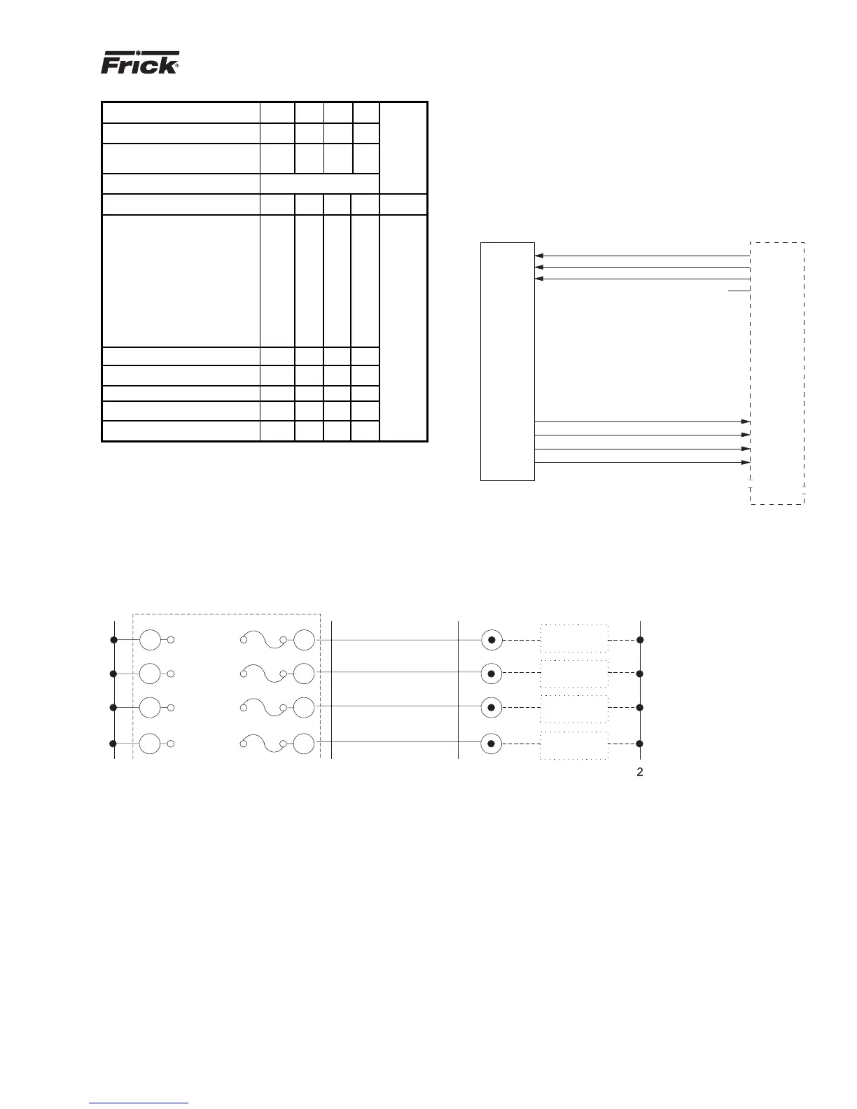
C - A master sequence controller must be installed to pro-
vide the signals to remote start and stop the compressors
and remote load and unload the compressors based on the
common suction pressure or other parameter and the com-
pressor status based on the optional microprocessor output
data feedback. The customer may supply his own master
sequencer panel (usually a programmable controller) or
Frick, can supply this sequencer if desired (contact Frick
Company for pricing).
MASTER SEQUENCE CONTROLLER (USUALLY
PROGRAMMABLE CONTROLLER) I/O
(TYPICAL FOR EACH COMPRESSOR)
RWB II COMPRESSOR
WITH MICROPROCESSOR
(TYPICAL FOR EACH COMPRESSOR)
INPUTS
OUTPUTS
RUN COMPRESSOR
LOAD COMPRESSOR
UNLOAD COMPRESSOR
SPARE
BIT 1
BIT 0
BIT 2
BIT 3
INPUTS
OUTPUTS
MASSEQ1
MICROPROCESSOR OUTPUT DATA CODE
A 3.5 K OHM, 10 watt resistor (RES) must be field installed, as shown below, when the 120 VAC outputs of the RWB II PLUS are
driving 120 VAC solid state input devices such as programmable controllers.
10%
20%
30%
40%
50%
60%
70%
80%
90%
100%
0
0
0
0
1
1
1
1
0
0
0
0
0
0
0
0
0
0
1
1
1
0
1
1
0
0
1
1
0
0
1
1
2
3
4
5
6
7
8
9
A
PROGRAMMABLE CONTROL
DATA CODE BIT 3
DATA CODE BIT 2
DATA CODE BIT 1
DATA CODE BIT 0
RES
NEUTRAL
OUTPUT
HOT
5
16
15
14
13
31
32
33
34
47
45
46
44
42
43
41
48
RES
RES
RES
PROGRAMMABLE CONTROL
PROGRAMMABLE CONTROL
PROGRAMMABLE CONTROL
OUTPUT
OUTPUT
OUTPUT