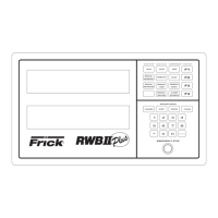
RWB II PLUS MICROPROCESSOR CONTROL
OPERATION
S70-200 OM
Page 4
KEYS AND KEY FUNCTIONS
NOTE: The microprocessor will automatically return to
the main operating display after 60 seconds of keybo-
ard nonactivity.
The [CHANGE] key rotates the dual display screen through
six display modes. The [CHANGE] key is also used to change
the status of various setpoints.
The [STEP] key steps or moves a set of flashing brackets
through the variable setpoints on the Adjustable setpoints
display, the Auto-cycle display, the Security display and the
Setback display. The setpoint enclosed within the flashing
brackets may be changed or updated. The [STEP] key is
also used when the annunciator display is selected to step
through the annunciator’s four information displays.
NOTE: The [ * ] key is used to step or move the flashing
brackets, described above, backwards.
The [ENTER] key is used to enter new setpoint limits.
The [CLEAR] key will reset an alarm or cutout indication on
the annunciator screen and will clear the microprocessor to
allow continued operation or restarting if all conditions have
returned to normal and no other control lockouts are in force.
The [NUMERIC KEYPAD] is used to introduce new setpoint
limits.
The [+/-] key is used to toggle between pounds per square
inch gauge (g) and inches of mercury (hg).
The [RUN], [STOP], and [REMOTE START] keys control
the starting and stopping of the compressor unit.
The [ALARM SILENCE] key will de-energize the alarm horn
output.
The [AUTO], [REMOTE], and [MANUAL] keys control the
operation of the compressor slide valve and moveable slide
stop.
The [F1] function key will return the operator to the main
operating display. This function may be invoked at any time,
even during setpoint entry.
The [F2] function key will call up the Security display. NOTE:
Press the [F2] key, as prompted by the display, to return
to the previously selected display.
The [F3] function key will call up the Setback display. NOTE:
To exit the Setback display, press the [F1] key as
prompted by the display.
The [F4] function key will call up the Auto Cycle display.
NOTE: To exit the Auto Cycle display, press the [F1] key
as prompted by the display.
The [DISPLAY BACKLIGHT] key will toggle the dual LCD
display backlights on and off. A preset delay will shut off the
backlight after ten minutes elapsed time.
The microprocessor has two liquid crystal displays in an 8
line by 40 character format, for a total of 320 characters.
There are 9 different display modes. When power is first
applied to the control panel, the unit will be in the Operating
display mode. To change to a different display mode, press
the [CHANGE] key. The display modes in their order of rota-
tion are:
1. Operating display
2. Adjustable Setpoints display
3. Adjustable Setpoints display #2
4. Fixed Setpoints display
5. Annunciator display (4 pages)
6. Shutdown Record display
7. Freeze display
[F1] Operating display
[F2] Security display
[F3] Setback display
[F4] Auto Cycle display
NOTE: On initial powering of the microprocessor, and
any time power has been removed from the micropro-
cessor, only the Operating, Setpoints, Annunciator, and
Shutdown displays will display information. The freeze
display will appear as a dark screen. The Freeze display
will only be present after a compressor unit cutout and
power has not been interrupted to the microprocessor.
The cutout must be on a safety setpoint. When power is
lost to the micro, it will not show the freeze display.
OPERATING DISPLAY *
OPERATING DISPLAY: Thu 10-01-87 15:33:36
Suction Disch Oil Filter Compressor
20.0 g 180 g 170 g 01PSID MAN Mode
+015 F 140 F 135 F RUNNING
V Ratio S V Pos Pump %FLA Sep 132 F
4.6 090% OFF 080% HTR off
Auto D Auto L FORCED UNLD ALARM
C.C.=20.0 g LOW-BATTERY
*Display for illustrative purposes only.
The Operating display is continuously updated and provides
a variety of information in regard to the current status of the
compressor’s condition and performance.
The information furnished by the Operating display is as fol-
lows:
The DAY, DATE, and TIME are displayed at the top right of
the display.
NOTE: To set day, date, and time; see TO CHANGE THE
ADJUSTABLE SETPOINTS.
SUCTION - Suction Pressure and Temperature are mea-
sured at the compressor inlet and are, respectively, displayed
in pounds per square inch gauge (g) or inches of mercury
(hg) and degrees Fahrenheit.
DISCH - Discharge Pressure and Temperature are measur-
ed at the compressor outlet and are, respectively, displayed
in pounds per square inch gauge (g) and degrees Fahrenheit.
OIL - Oil Pressure and Temperature are measured prior to
entering the compressor and are, respectively, displayed in
pounds per square inch gauge (g) and degrees Fahrenheit.
FILTER - Pressure drop across the oil filter. On the model
676 only, the bearing oil filter pressure drop is displayed.
The main oil injection feed filter pressure drop is shown on a
unit mounted gauge.