The detector and magnet should be mounted
using the double sided adhesive pads or screws
provided.
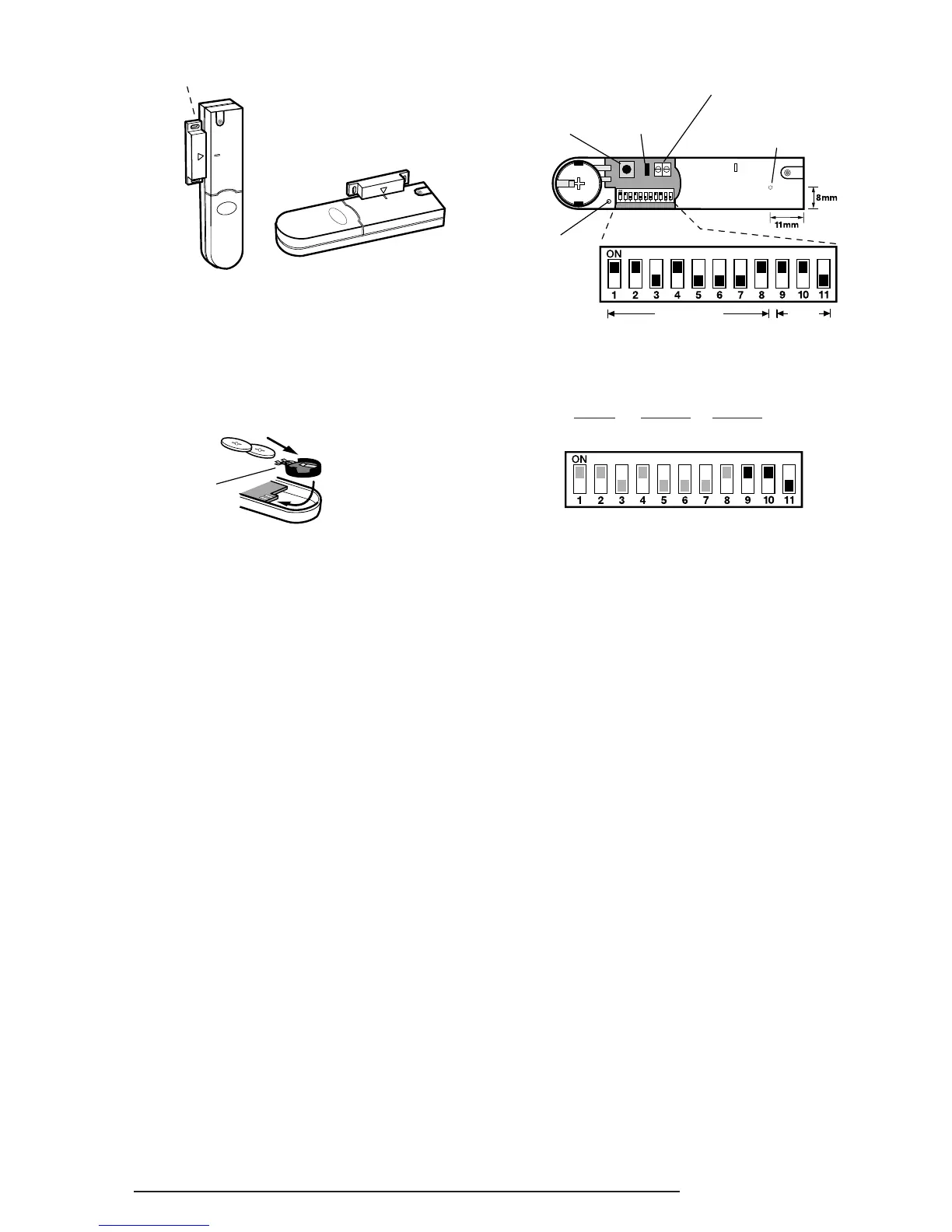
3. If fixing the detector with screws first remove the
battery holder by carefully tilting up the end and
pulling away from the printed circuit board.
The top of the detector is secured with a keyhole
slot over the head of the smaller pan head screw
and the bottom of the detector is secured using
the 12mm counter-sunk head screw fitted within
the battery compartment. Carefully drill out the
centre of the fixing screw hole in the battery
compartment using a 3mm drill. Fit the magnet
using the two 15mm fixing screws. Do not over-
tighten the fixing screws as this may distort or
damage the casing.
4. If an additional wired Magnetic Contact is
required, this should be wired to the terminal
block provided in the battery compartment. The
wired contact should be connected using two
core (24AWG) wire of maximum length 1.5m. A
cable entry cut-out is provided beside the
terminal block in the battery cover.
If an additional wired contact is connected to the
detector then jumper link S2 on the PCB must be
removed.
IMPORTANT: If an additional wired contact is not
connected, then the jumper link S2 must be fitted
for the detector to operate correctly.
5. Configure the House Code for the Magnetic
Contact Detector by setting DIP switches 1-8 to
the same ON/OFF combination as the House
Code DIP switches in all other system devices.
6. DIP Switches 9-11 must be set as follows for use
with this alarm system:
DIP 9 DIP 10 DIP 11
ON ON OFF
7. Slide the two batteries supplied into the battery
holder, ensuring that the positive (+) side is
uppermost on each battery as it is installed.
8. If necessary, refit the battery holder into the
detector ensuring that the spring clip connectors
slide onto either side of the circuit board.
9. Refit the battery cover.
TESTING THE MAGNETIC CONTACT
DETECTORS
Ensure that the system is in Service Mode, (see
page 17).
1. Remove the battery cover from the detector.
The LED on the detector will illuminate for approx
1s as the battery cover is removed to indicate that
the tamper switch has been activated.
2.
Open the door/window to remove the magnet from
the detector. As the magnet is moved away from
the detector the LED will illuminate for approx. 1s to
indicate that the Detector Contact has been triggered.
3.
If any external Magnetic Contact Sets are connected
to the detector, operate these one at a time. Each time
a contact is opened the LED on the detector should
illuminate for 1s to indicate that it has been triggered.
4. Replace the battery cover on the detector.
 Loading...