EXTERNAL SOLAR SIREN
The Siren and Solar Panel are all encapsulated within
a tough polycarbonate housing. This housing provides
full protection against adverse weather conditions.
An LED indicator is built into the siren to act as a
visible deterrent/indication that the system is active.
The indicator LEDs will slowly and alternately flash
whether the system is Armed or Disarmed. During an
alarm condition the indicator LEDs will flash rapidly.
An integral anti-tamper switch provides additional
security protection to the Siren and will immediately
generate a full alarm should any unauthorised attempt
be made to interfere with and remove the siren cover.
The Siren is powered by a high capacity 6V/1.2Ahr
rechargeable sealed lead acid battery. A Solar Panel
mounted on the top of the housing charges the battery
during daylight hours. During darkness, only a small
amount of energy is required to operate the Siren unit.
A 9V Alkaline PP3 battery is supplied in the External
Siren to boost the initial power to the unit when the
system is first activated until the Solar Panel charges
the main battery. (This battery is only designed to last
for a short period until the main rechargeable battery
has obtained sufficient charge).
The Siren unit incorporates the installations Jamming
Detection system which will (if activated) generate an
alarm if any attempt is made to continuously jam the
radio channel used for the system.
POSITIONING THE SOLAR SIREN
The Siren should be located as high as possible in a
prominent position so that it can be easily seen and
heard. The Siren should be mounted on a sound flat
surface so that the rear tamper switch is not activated
when mounted. Ensure that the tamper switch does
not fall into the recess between brick courses as this
could prevent the switch from closing and give a
permanent tamper signal.
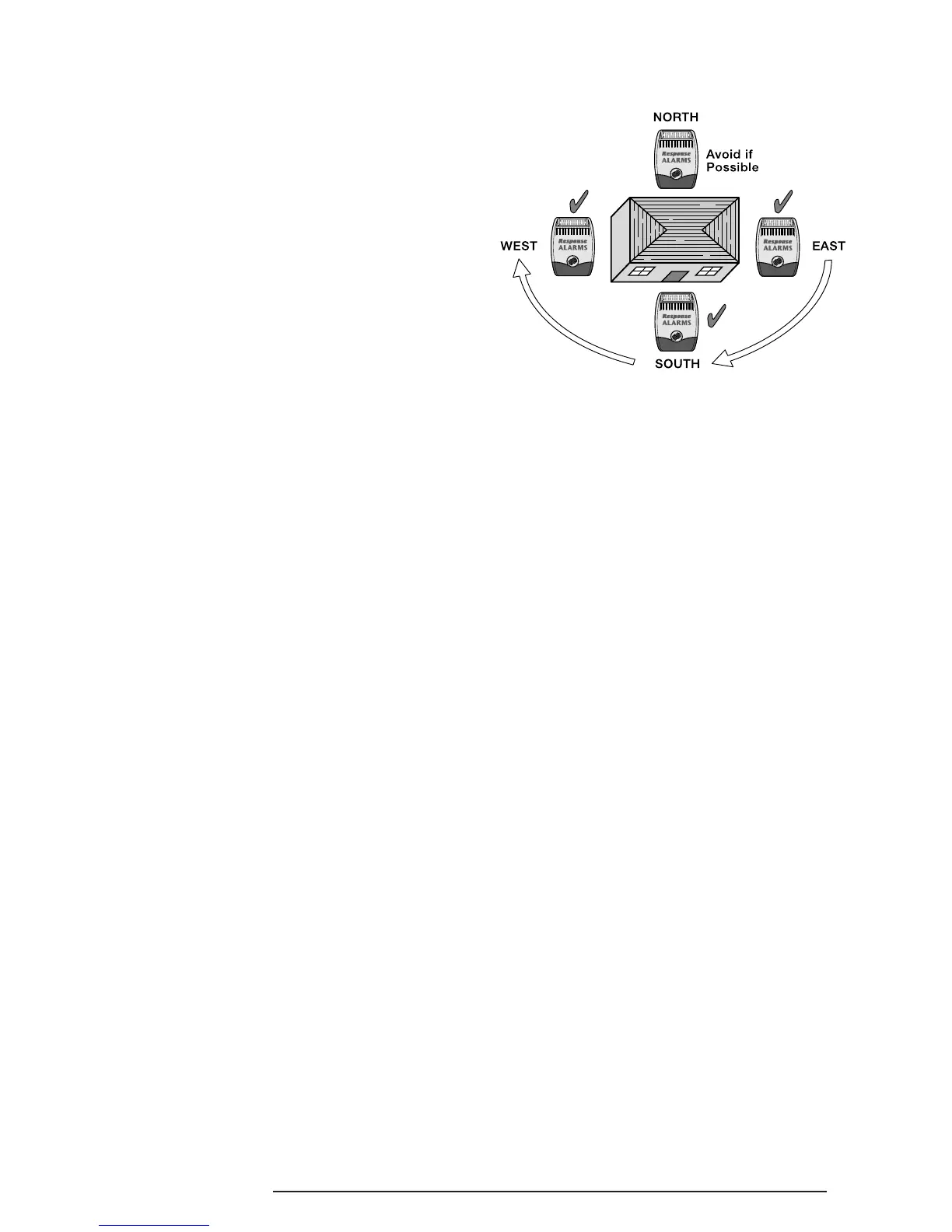
In order to provide the maximum amount of daylight
to the Solar Panel, the siren should ideally be mounted
on a south facing wall. However, an easterly or
westerly position will suffice.
Mounting the device on a north facing wall should be
avoided as this could mean that during the short dark
days of winter months the solar panel may not receive
sufficient daylight in order to maintain the battery
charge at acceptable levels.
Shadows cast by neighbouring walls, trees and roof
overhangs should also be avoided. If the Siren is to be
mounted below the eaves, it should be positioned a
distance of at least twice the width of the eaves
overhang below the eaves. Remember that in winter
the sun is lower in the sky and you should avoid winter
shadows where possible.
The External Solar Siren contains a sophisticated
radio receiver. However, reception of radio signals can
be affected by the presence of metallic objects within
the vicinity of the Receiver. It is therefore important to
mount the Solar Siren a minimum distance of 1m away
from any external or internal metalwork, (i.e.
drainpipes, gutters, radiators, mirrors etc.).
It is recommended that you check the suitability of
your chosen location for the Solar Siren by temporarily
fitting it to the external wall. Using the Remote
Control, (as described below) power up the Siren and
check that you can operate the Siren from in and
around the property, and from all locations where you
plan to install detectors.
INSTALLING AND CONFIGURING
THE SOLAR SIREN
1. Remove the fixing screw from the bottom edge of
the Siren housing and carefully hinge off the front
cover. All electronic components are housed
within the front cover.
2. Hold the mounting plate in position and mark the
positions of the four mounting holes. A spirit level
placed on the casing will ensure a perfect level.
3. Fit two 30mm fixing screws in the top holes leaving
approximately 10mm of the screw protruding.
SA1, SA2(PF), SAC1 5