SYSTEM ARMING
The system has an ‘Instant-Arm’ and Delay-Arm’ mode.
If the system is armed in ‘Instant-Arm’ mode then all
detectors will immediately become fully armed. Any
detector triggered while the system is armed will
immediately initiate a full alarm condition.
ENTRY/EXIT DELAY
If the system is armed in ‘Delay-Arm’ mode this will
activate the system with a fixed 15 second entry/exit
delay period. This allows a 15 second period for the
user to exit the property after setting the system with
the Remote Control or at the Keypad. Any detector
triggered while the system is armed will not cause an
alarm condition until after the 15 second entry/exit
delay has expired. This allows time for the system to
be Disarmed before an alarm condition is triggered
when re-entering the property.
Note: To conserve power and maximise battery life
the PIR Detector will only detect movement if there
has been no movement detected within the previous
2 minutes. Consequently the PIR Detector will not
become active until the protected area has been free
from movement for more than 2 minutes.
ZONE LOCKOUT
If a detector is triggered while the system is armed an alarm
condition will occur. After the set alarm duration has expired
the alarm will stop and the system will automatically reset.
Subsequent detectors triggered will again initiate an alarm
condition. However, after an alarm condition has been
initiated three times the system will be ‘Locked Out’ and will
not reset, any further alarm signals from detectors will be
ignored until the system is disarmed.
TAMPER PROTECTION
All system devices (except any Remote Control Units)
incorporate Tamper protection features to protect
against unauthorised attempts to interfere with the
device. Any attempt to remove the battery cover from
any device (except a Remote Control) or to remove the
Solar Siren from the wall will initiate an alarm condition
(unless the system is in Service Mode), even if the
system is Disarmed.
JAMMING DETECTION
In order to detect any attempts to illegally jam the radio
channel used by your alarm system, a special jamming
detection function is incorporated into the Solar Siren.
If this feature is enabled, and the radio channel is
jammed continuously for 30 seconds, when the system
is armed, the Solar Siren will emit a pre-alarm series of
rapid bleeps for 5 seconds. If the jamming continues
for a further 10 seconds or more a full alarm condition
will occur. In addition if the system is jammed for more
than three periods of 10 seconds in a 5 minute interval,
this will also generate a Full Alarm condition.
The Jamming Detection circuit is designed to
permanently scan for jamming signals. However, it is
possible that it may detect other local radio interference
operating legally or illegally on the same frequency. If it
is planned to operate the jamming detection feature we
recommend that the system is monitored for false
jamming alarms for at least 2 weeks prior to leaving the
Jamming Detection function permanently enabled.
BATTERY MONITORING
All devices powered by non-rechargeable batteries
incorporate a battery level monitoring feature which
will warn of a low battery status. The batteries on any
device indicating a low battery status should be
replaced immediately.
SYSTEM HOUSE CODE
In order to prevent any unauthorised attempt to
operate or disarm your system, you must configure
your system to accept radio signals only from your own
system devices. This is done by setting a series of
eight miniature (DIP) switches in all devices to the same
ON/OFF combination (the House Code) selected by
the user/installer. All detectors and Remote Control
Unit(s) must be configured with the same House Code
in order for the system to operate correctly.
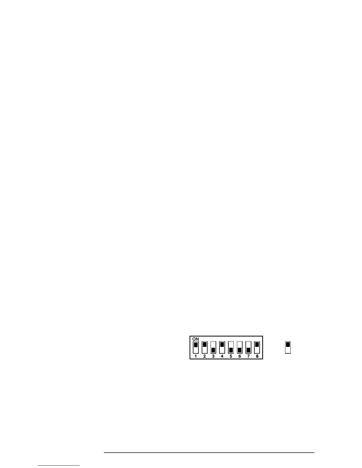
Inside the detectors and Remote Control Unit is a
series of 8 DIP switches.
The House Code is set up by moving each of the 8
switches in each device to the same randomly
selected ON/OFF sequence. When setting the DIP
switches, ensure that each switch ‘clicks’ fully into
position. Use the tip of a ballpoint pen or a small
screwdriver to move each switch in turn.
Note: It is recommended that the system House
Code is always changed to a code other than
the factory.
INTRODUCTION AND OVERVIEW
SA1, SA2(PF), SAC1 3