2.2.3
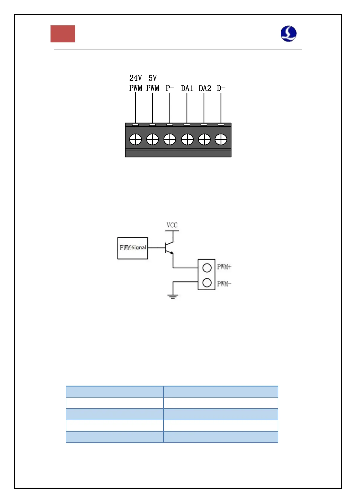
J02PWM/DA Terminals
Figutr 4 PWM/DA Terminals
BCL4566E has 2 channels of PWM pulse width modulation signal, the left channel is
24V level PWM. The right channel is 5V level PWM, and P- is the negative terminal of the
PWM signal. The duty cycle is adjustable from 0% to 100%, and the highest carrier
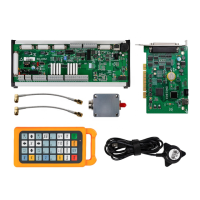
frequency is 50KHz. The signal output mode is shown in the figure below.
Figure 5 PWM Output Circuit
Note: 1) There are dedicated enabling relays for PWM+ and PWM- signals, and there is no need
for external relay isolation.
2) Wrong connection of 5V/24V PWM signal may cause damage to the laser.
BCL4566E has 2 channels of 0~10V analog output. DA1/DA2 is the positive terminal of analog
quantity, and D- is the negative terminal of analog quantity. DA1/DA2 can be configured as
the control signal of laser peak power and gas proportional valve in the "Cypfig" that comes
with CypcutE software.