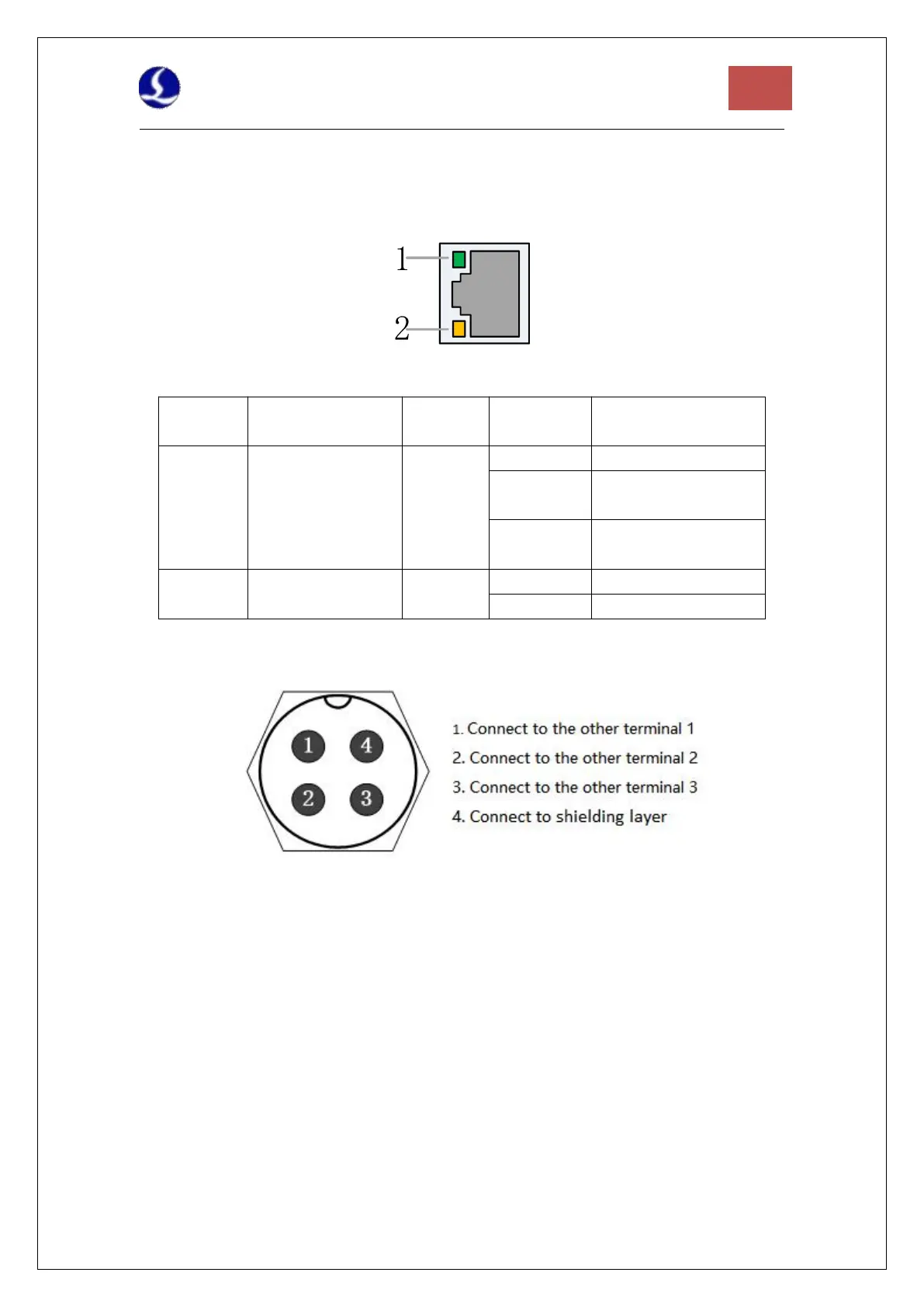
2.2.6 J09/J10 Network Interface
J09 is the EtherCAT network output interface, and J10 is the EtherCAT network input interface,
supporting 100Mbps network communication. It is recommended to use standard RJ45
network cables in CAT5E or up for bus communication
Description of RJ45 connection status of network terminal
EtherCAT Bus
Connection and
Communication
Status
Connected, without
communication
Connected, with
communication
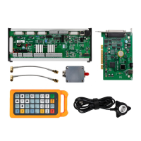
2.2.7 J11 Sensor Interface
Figure 8 Sensor interface
The 4-core signal transmission cable of the sensor can be made by yourself with a 3-core
shielded cable and two 4-pin plugs. 1, 2, and 3 cores are connected in pairs, and the 4th core
must be connected with a shielding layer. It is recommended to use the original cable to
ensure stability.
2.2.8 J12DB15 Servo Axis Interface
The control interface of BCL4566E focusing servo driver is double-row female DB15F, and the
pin definition of the corresponding wire is shown in the figure below: