Distinguish the positive and negative wires of the power supply in color, e.g.,the red
wire is connected to the positive pole, and the blue wire is connected to the negative
pole
Loads with relatively large interference (e.g. servos and solenoid valves) are powered
separately from the controller.
2. Grounding
The ground wiring adopts the standard two-color, yellow and green, wires.
It is recommended to use multi-point grounding, for some high-frequency signals (PWM,
pulse, encoder, capacitance, etc.) in the laser cutting machines.
The machine tool uses galvanized grounding screws and a special grounding wire for
grounding. The resistance between the grounded metal body and the main grounding
point should be ≤ 0.1Ω.
3. Signal (Control)
Signal wire color, e.g. black.
Choose the signal wire according to the power.
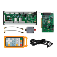
DC 24V solenoid valve is recommended. Add absorption circuits at both ends of the
solenoid valve, that is, connect a freewheeling diode in parallel at both ends of the
solenoid valve (pay attention to the direction, withstand current, and withstand voltage),
as shown in the figure below.
It is recommended that the digital signal (PWM) shielding layer be grounded at both
ends, and the analog signal (DA) shielding layer be grounded at one end. Single-ended
grounding can avoid low-frequency current noise on the shielding layer; double-ended
grounding can effectively eliminate high-frequency interference. If the transmission
cable is very long, it is recommended to ground at multiple points to ensure that the
shielding layer is at the same potential.
The resistance from the cutting head connected to the amplifier to the shell of the
machine tool is ≤ 1Ω, and the resistance to the grounding point of the electrical cabinet
is ≤ 6Ω.
4. Notes