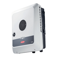
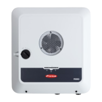
Do not install the inverter with the connections upwards on a vertical
wall or column.
Do not install the inverter overhanging with the connections upwards.
Do not install the inverter overhanging with the connections down-
wards.
Do not install the inverter on the ceiling.
General Location
Selection
Please note the following criteria when choosing a location for the inverter:
4 i
n.
100 m
m
4 i
n.
100 m
m
8 i
n.
200 m
m
-40 °F -
+
1
40 °F
-4
0 °C - +60 °C
0 -
100 %
Only install on a solid, non-flammable surface
Max. ambient temperatures: -40 °F/+140 °F (-40 °C/+60 °C)
Relative humidity: 0–100%
The air flow direction within the inverter is from right to top (cold air intake on the right,
hot air outflow at the top). The waste air may reach a temperature of up to 70 °C.
When installing the inverter in a switch cabinet or similar closed environment, it is
necessary to make sure that the hot air that develops will be dissipated by forced-air
ventilation
11
EN-US
 Loading...
