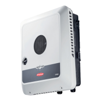
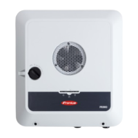
1/2 in. for data communication cable (DATCOM)
3/4 in.
- 1 1/4
in.
for AC and DC cables
* A grounding electrode terminal (GET) may be required depending on local regu-
lations.
The cable for the grounding electrode terminal can be fed through the designated
opening on the underside of the wall bracket.
IMPORTANT! The knockouts on the rear of the wall bracket are made of metal.
Knocking or
Drilling Out
Knockouts
IMPORTANT! The knockouts on the underside of the mounting bracket may be knocked
out using a hammer or screwdriver, drilled out using a step drill, or opened using a hole
punch. The side knockouts and the knockouts at the back may only be drilled out with a
step drill or opened with a hole punch.
IMPORTANT! You should only remove the minimum number of knockouts required for
the available cables.
Use suitable eye protection when knocking/drilling out the knock-
outs.
Only knock out knockouts using a hammer or screwdriver from the
inside outwards.
Only use suitable step drills to drill out the knockouts.
Do not use spiral drills for drilling out!
Only drill out knockouts using a step drill from the outside inwards.
When drilling out using a step drill, ensure that the inside of device
(e.g. connection block) is not damaged.
When drilling out the knockouts at the back, place the mounting
bracket on an even surface with the back upwards so that shavings
and pieces of metal can fall out of the mounting bracket.
Attach appropriate conduits to all knocked/drilled out knockouts.
In the event of installation outside, only use watertight conduits and
conduit fittings.
Conduits and conduit fittings are not included with the inverter.
If necessary, deburr the number of knockouts required with a suit-
able tool.
19
EN-US
 Loading...
