26
Connection Options and Knockouts on the Fronius
IG TL
Connection op-
tions on the Fro-
nius IG TL
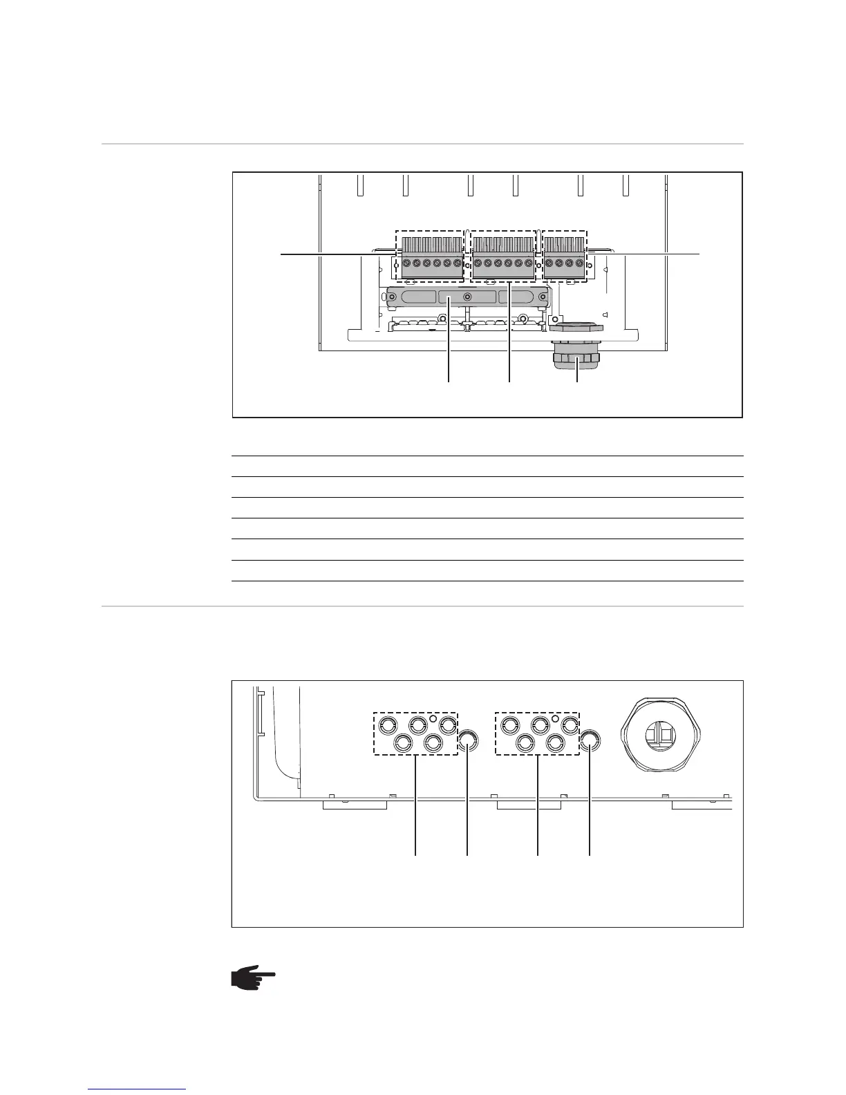
Connection options on the wall bracket of the Fronius IG TL
Knockouts on the
Fronius IG TL
The connection area contains several knockouts of different sizes. When knocked out, the
openings are used as inputs for the DC wires.
Knockouts on the Wall Bracket of the Fronius IG TL 5.0
Item Description
(1) DC+ terminals
(2) Strain relief device
(3) DC- terminals
(4) Metric screw joint M32 or M40 (AC connection)
(5) AC terminals
NOTE! You should only remove the number of knockouts required for the avail-
able cables (e.g., 3 openings for 3 module strings).