7
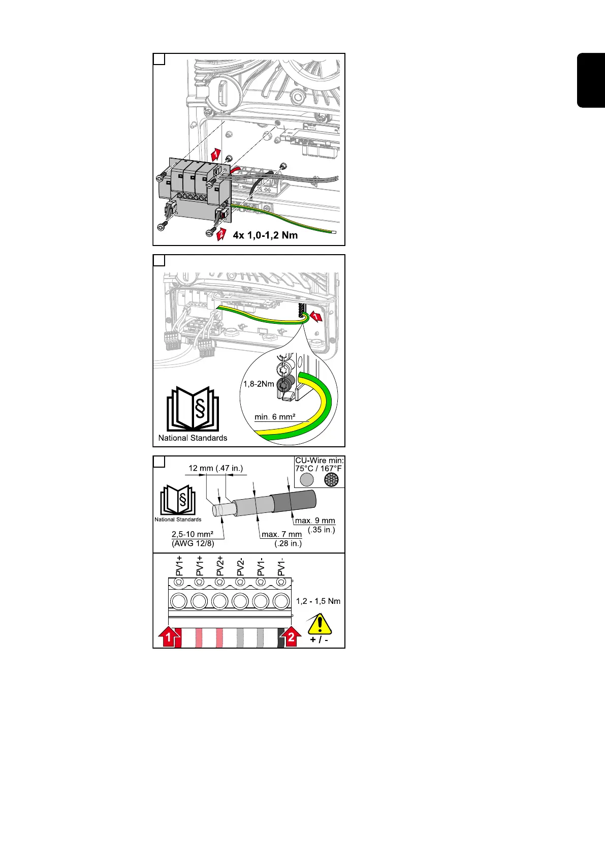
Insert the PC board into the inverter and
secure with the four screws (TX20) sup-
plied at a torque of 1.0 ‑ 1.2 Nm.
8
Fasten the ground conductor with a cross
section of at least 6 mm² to the ground
electrode terminal using a screwdriver
(TX20) and a torque of 1.8 - 2 Nm.
IMPORTANT!
Depending on national standards and
guidelines, a larger cross section of the
ground conductor may be required.
The use of other inputs can make it difficult
to insert the connection area divider or
damage the ground conductor.
9
Strip the insulation on the single conduct-
ors by 12 mm and secure to the corres-
ponding slot of the terminal on the PC
board with a torque of 1.2 - 1.5 Nm.
IMPORTANT!
The cable cross section must be selected
according to the specifications for the
respective inverter power category (see
chapter Permitted cables on page 54).
125
EN

 Loading...


