Insulation resist-
ance
WARNING!
An electric shock can be fatal! Some of the insulation resistance measurements
are taken under high voltage.
The process must be fully understood before starting the test. Observe the following
safety precautions:
▶
Only perform the measurement if a ground conductor resistance test has been car-
ried out successfully
▶
Restrict access to the work area as far as possible
▶
Do not touch any other person while performing the test and take measures to pre-
vent other people touching any metallic parts
▶
A voltage is applied to the area to be tested each time that the insulation resistance
measuring device is switched on. The insulation resistance measuring device must
be fitted with an automatic self-discharge device.
▶
Wear suitable protective clothing/protective equipment while conducting the test
▶
Ensure that the polarity is correct while conducting the insulation resistance test to
avoid unreliable test results
The main switch must be switched on.
With nominal (DC) battery charging system voltages £ 500 V ® the test voltage of the
measuring device is 500 V for all measurements *).
The insulation resistance must not fall below the following values *):
Measurement Measured value
Primary -> Earth ³ 1 MW
Secondary -> Earth ³ 1 MW
Primary -> Secondary ³ 2 MW
Communication -> Secondary ³ 2 MW
Communication -> Primary ³ 2 MW
Communication -> optional inputs ³ 2 MW
Legend:
Primary = AC (L1 and N) | Secondary = DC (DC+ and DC-)
Earth = PE | Communication = USB
*) These requirements comply with DIN VDE 0701-0702 and ÖVE/ÖNORM E8701‑1.
Also refer to the applicable requirements and standards in your country.
The insulation measurement must be taken between the following points:
DC+ and DC- should be short-circuited for this test on the battery charging system, oth-
erwise both DC inputs have to be measured separately.
N and L1 should be short-circuited for this test on the battery charging system, otherwise
both AC inputs have to be measured separately.
PE to Primary PE to Secondary
Primary to Secondary Communication to Secondary
Communication to Primary Communication to optional inputs
Use an adapter to short-circuit DC+ / DC- / AC / Communication and optional inputs dur-
ing this measurement.
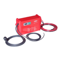
Only use the original charging leads and mains cable for taking the measurements.
49
EN