Location of the primary meter at the feed-in point. *Terminating resistor R 120 Ohm
The following must be observed in a multi-meter system:
-
Connect the primary meter and the battery to different channels (recom-
mended).
-
The remaining Modbus participants must be distributed equally.
-
Only assign each Modbus address once.
-
Terminating resistors must be positioned individually for each channel.
Menu structure A graphic view of the menu structure can be found in the User Information that
is supplied as standard.
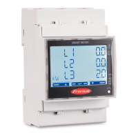
Setting the ad-
dress of the
Fronius Smart
Meter
Symbol Name Event Function
Prog
1 x
Increases the set value
Prog
2 seconds
Proceeds to the next menu item
1
Press "Prog" for 2 seconds to call
up code entry.
2
Enter the password "2633". In-
crease the value with "Prog".
17
EN