Installation
Checklist for in-
stallation
For installation information, see the following chapters:
1
Switch off the power supply before establishing a mains connection.
2
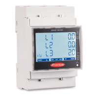
Mount the Fronius Smart Meter (see Mounting on page 8).
3
Connect automatic circuit breakers or automatic circuit breakers and discon-
nectors (see Protective circuit on page 8).
4
Connect the mains cable to the Fronius Smart Meter (see Cabling on page
9).
5
Connect the output terminals of the Fronius Smart Meter to the Fronius in-
verter (see Connecting the data communication cable to the inverter on
page 9).
6
If necessary, set terminating resistors (see Terminating resistors on page
11).
7
Tug on each wire and plug to make sure that they are securely connected to
the terminal blocks.
8
Switch on the power supply to the Fronius Smart Meter.
9
Check the firmware version of the Fronius inverter. To ensure compatibility
between the inverter and the Fronius Smart Meter, the software must always
be kept up to date. The update can be started via the inverter web page or
using Solar.web.
10
If several Fronius Smart Meters are installed in the system, set the address
(see "Setting the address" under Setting the address of the Fronius Smart
Meter on page 17).
11
Configure and commission the meter (see Start-up on page 21).
Mounting The Fronius Smart Meter can be mounted on a 35 mm DIN rail. The housing
comprises 2 modules according to DIN 43880
Protective cir-
cuit
The Fronius Smart Meter is a hard-wired device and requires a disconnecting
device (circuit breaker, switch or disconnector) and overcurrent protection (auto-
matic circuit breaker).
The Fronius Smart Meter consumes just 10-30 mA, so that the nominal capacity
of all switches, disconnectors, fuses and/or automatic circuit breakers is determ-
ined by the wire gauge, mains voltage and required breaking capacity.
-
Switches, disconnectors and circuit breakers must be within sight and loc-
ated as close as possible to the Fronius Smart Meter; they must also be easy
to use.
-
Use automatic circuit breakers that are rated for max. 63 A.
-
To monitor more than one mains voltage, use connected automatic circuit
breakers.
-
The automatic circuit breakers must protect the mains terminal, which is
marked L1. In rare cases where the neutral conductor has overcurrent pro-
tection, the overcurrent protection device must interrupt both neutral and
non-earthed cables concurrently.
-
The circuit protection/disconnecting device must satisfy the requirements of
IEC 60947-1 and IEC 60947-3, as well as all national and local regulations
for electrical systems.
8