13 SEP 12
/ Battery Charging Systems / Welding Technology / Solar Electronics
Processes
Functional Tests
Step 1:
Step 1:Step 1:
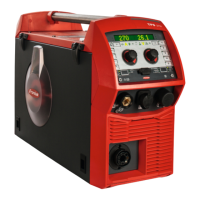
Step 1: Press the Parameter Selection button (A⁄ until the
main motor indicator (B⁄ is lit.
Step 2:
Step 2:Step 2:
Step 2: First test the motor without load by opening up the
drive rolls on the wire feeder
Step 3:
Step 3:Step 3:
Step 3: Press the Wire Feed button (C⁄ and check the left
most display (D⁄. It should be ~.7 amps (+/- 1
amp⁄.
Step 4:
Step 4:Step 4:
Step 4: Check the motor under load by closing the drive
rolls on the wire feeder
Step 5:
Step 5:Step 5:
Step 5: Press the Wire Feed button (C⁄ and check the left
most display (D⁄. It should be ~1.0 amps. (+/-
20%⁄
A
AA
A
B
BB
B
C
CC
C
D
DD
D
Step 1:
Step 1:Step 1:
Step 1: Press the Parameter Selection button (A⁄ until the
voltage indicator (B⁄ is lit.
Step 2:
Step 2:Step 2:
Step 2: Disconnect the ground connection from the front of
the power supply.
Step 3:
Step 3:Step 3:
Step 3: Press the process select button (C⁄ until the Stick
indicator (D⁄ lights up.
Step 4:
Step 4:Step 4:
Step 4: The right most display (E⁄ should indicate 40V
within one minute.
Step 5:
Step 5:Step 5:
Step 5: Press the process select button (C⁄ until the
process changes to something other than TIG or
Stick.
A
AA
A
B
BB
B
C
CC
C
E
EE
E
Motor Draw Test
Motor Draw TestMotor Draw Test
Motor Draw Test
Output
Output Output
Output Voltage
VoltageVoltage
Voltage Test
TestTest
Test
D
DD
D
-
--
- 54
54 54
54 -
--
-